
Backlight Design for Industrial TFT LCD and HMI Display Modules
Part of: High-Brightness TFT LCD Engineering
·Senvita Display Engineering
In industrial TFT LCD and HMI display modules, the backlight is often the subsystem that determines readability, power draw, temperature rise, service life, and long-term field reliability. Whether an operator interface remains legible in a factory line, outdoor cabinet, rail application, medical panel, or vehicle-mounted terminal is rarely decided by the LCD cell alone. It is decided by the engineering of the LED backlight topology, constant-current driver, dimming method, thermal path, and optical stack. This guide explains the practical design tradeoffs behind industrial backlights so HMI engineers can make better decisions on brightness, uniformity, EMI, lifetime, and cost. If you are still at the platform selection stage, start with our related guide on how to choose a TFT LCD for industrial HMI.
Why industrial HMI backlight design requires a different mindset
Consumer displays optimize aggressively for thinness, headline brightness, and BOM pressure. Industrial HMI modules operate under a different set of priorities: 24/7 duty cycles, wide ambient temperature, power rail variation, sealed enclosures, high ambient light, long product life, and controlled revision management. In this environment, the backlight is not a cosmetic feature. It is a cross-disciplinary subsystem linking power electronics, optics, mechanical design, thermal engineering, EMC, and supply-chain control.
In real projects, the most common backlight failures are not dramatic LED burnouts. They are gradual and expensive problems: brightness dropping faster than expected, cold-start instability, PWM dimming causing camera banding, direct-lit hot spots, boost-switching noise coupling into touch or display interfaces, and high-temperature chromatic shift that exceeds maintenance windows. That is why industrial backlight design should be planned early, not patched late by simply increasing LED current after a prototype misses its brightness target.
LED backlight topologies: edge-lit vs direct-lit for industrial TFT LCD
Edge-lit backlights: thin, efficient for medium brightness, common in HMI modules
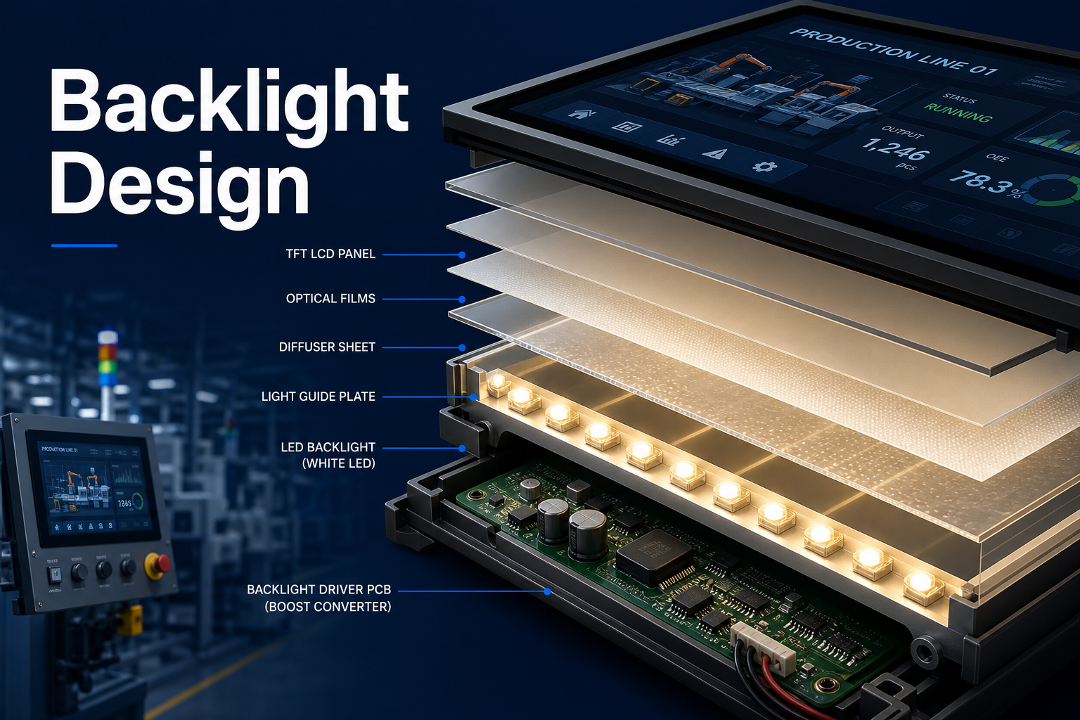
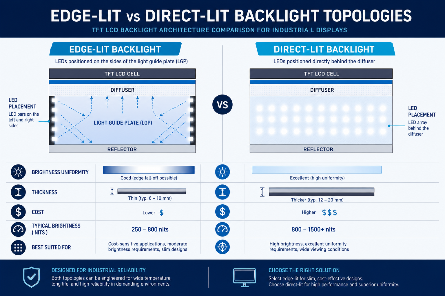
An edge-lit backlight places LED bars on one side, two sides, or all four sides of the display. Light is injected into a light guide plate, then redistributed by microstructures and shaped by diffuser films, brightness enhancement films, reflective films, and the LCD polarizer stack. This architecture is thin, cost-effective per area, and highly common from 4.3-inch to 15.6-inch industrial HMI products where mechanical depth is limited.
The engineering challenge in edge-lit design is not just how many LEDs are used. Performance depends on LED pitch, coupling efficiency into the light guide, the scattering pattern of the LGP, the reflectivity of the cavity, LED bin consistency, and the way the frame recovers stray light. A frequent mistake is trying to move from 500 nits to 1000+ nits by only raising current. In practice, higher current can quickly worsen edge hot spots, thermal stress, and life. A two-bar topology, thicker light guide, or revised optical film stack is often the better solution.
Direct-lit backlights: stronger high-brightness potential, more mixing depth required
A direct-lit backlight distributes LEDs behind the LCD area and uses a mixing cavity plus diffusers to create uniform surface emission. This makes it naturally attractive for high-brightness HMI, larger displays, outdoor readability, and applications where more mechanical depth is acceptable. Compared with edge-lit systems, direct-lit designs often spread thermal load better at 1000 to 1500 nits and above because the power is distributed across more emitters.
The tradeoff is thickness, LED count, and tighter sensitivity to mixing distance and mechanical tolerances. If cavity depth is insufficient, if LED pitch is too large, or if the diffuser stack is not optimized, LED signatures and hot spots will be visible. In direct-lit designs, cavity reflectance, LED placement, diffuser haze, and frame shadowing all have a first-order effect on uniformity.
LED bar count, series strings, and light guide plate considerations
For edge-lit modules, common configurations include single-edge single-bar, dual-edge dual-bar, top-and-bottom bars, and four-edge injection. More bars generally improve mixing and brightness headroom while reducing the burden on each LED, but they also increase channel count, assembly complexity, and cost. In many 7-inch class HMI modules, a single edge bar is sufficient for 300 to 600 nits. Once targets move into the 800 to 1000 nit range, dual-edge solutions are often more robust. For high-brightness industrial designs, including modules in the class represented by our industrial TFT display example product page, optical and thermal upgrades usually have to be planned together.
The light guide plate is not a passive slab. It is a precision optical element that controls extraction efficiency and luminance distribution. Its thickness, material transmission, extraction dot gradient, edge polishing, and reflective boundary conditions all matter. As a rule, extraction features should become stronger farther away from the LED injection edge to compensate for path loss. But if extraction becomes too aggressive, total efficiency drops and near-edge dark bands can appear. For industrial projects, suppliers should be able to provide not just a typical brightness number, but luminance maps of the bare backlight, the assembled module, and the module at elevated temperature.
| Topology | Typical strengths | Main limitations | Best-fit HMI scenarios |
|---|---|---|---|
| Edge-lit single bar | Thinnest structure, low cost, simple drive | Limited headroom for very high brightness, edge hot-spot risk | Indoor panels, standard industrial controls |
| Edge-lit dual bar | Balanced brightness and uniformity | Bar matching and mechanical accuracy matter | Mid- to high-brightness HMI |
| Edge-lit four side | Good large-area uniformity | Higher cost, harder optical tuning | Larger premium displays |
| Direct-lit | Strong high-brightness capability, distributed thermal load | Thicker stack, mixing-depth and hot-spot sensitivity | Outdoor, sunlight-readable, larger displays |
Driver IC selection: boost topology, constant current, and dimming architecture
Why boost constant-current drivers dominate industrial TFT backlights
Industrial backlights typically use strings of white LEDs. Since a single white LED may have a forward voltage around 2.8 to 3.4 V, a practical string of 6 to 12 LEDs often exceeds common system rails. That is why boost LED drivers are widely used, with buck-boost or SEPIC variants where the input rail is highly variable. For HMI engineers, the important parameters are not just maximum current. They include current accuracy, channel matching, fault protection, dimming range, switching frequency planning, and EMI behavior.
Simple constant-voltage schemes with resistive limiting are usually poor practice in industrial products because LED forward-voltage variation, temperature coefficients, and aging drift will directly cause non-uniform brightness and inconsistent life. A constant-current driver keeps each string controlled across temperature and tolerance. In multi-bar designs, this is essential for preventing one side from aging or appearing brighter than the other. If the system needs backlight fault monitoring, redundancy, or segmented control, a multi-channel driver with current reporting and open/short diagnostics is a strong advantage.
PWM vs DC dimming: use the right method for the use case
PWM dimming controls average luminance by switching LEDs on and off at a fixed current. It preserves chromaticity better, offers wide dimming range, and is easy to linearize. DC dimming changes the LED current directly. It can be quieter electrically and lower-risk for visible flicker, but at low current it may shift color, reduce matching, and complicate low-brightness behavior. For industrial HMI, the most practical approach is often hybrid dimming: use analog or DC current adjustment in the upper brightness range to reduce switching noise, then use high-frequency PWM in low-brightness regions to preserve color stability and deep dimming performance.
If the product integrates cameras, barcode engines, or machine-vision sensors, dimming frequency must be chosen to avoid rolling-band artifacts and beat effects. We cover that topic in more detail in our article on flicker analysis for industrial displays. At the same time, fast backlight switching edges and long LED loop paths can become an EMI source, so the driver selection and PCB layout should also be reviewed together with the guidance in our EMI troubleshooting article for industrial display systems.
Driver IC selection checklist
- Input voltage range compatible with 5 V, 12 V, 24 V, battery, or adapter variation
- Boost output headroom sufficient for worst-case LED forward voltage, low temperature, and aging margin
- Current accuracy and channel-to-channel matching suitable for visible uniformity requirements
- PWM dimming frequency range high enough, with external synchronization if needed
- Protection features for open LED, short LED, over-temperature, under-voltage, and over-voltage
- Switching frequency planned to avoid touch, wireless, audio, or imaging-sensitive bands
- Support for analog dimming, digital control, or local MCU-managed brightness curves
| Drive strategy | Advantages | Risks | Recommended use |
|---|---|---|---|
| Pure PWM dimming | Stable color, wide dimming range | Camera or human-visible flicker risk, stronger EMI pressure | Systems needing large dynamic range with validated frequency control |
| Pure DC dimming | Low flicker risk, simpler average power behavior | Low-brightness color shift, weaker linearity | Fixed-brightness or mid/high-brightness equipment |
| Hybrid dimming | Balanced color stability, low-brightness behavior, and EMI | More control complexity and validation effort | Often the best option for industrial HMI |
Brightness targets in nits for indoor, outdoor, and high-brightness HMI
Brightness targets should always be set from the application environment, not from a competitor datasheet. Nits alone do not define readability. The real result depends on ambient illuminance, cover glass transmission, touch stack losses, anti-glare and anti-reflection treatment, polarizer efficiency, viewing distance, and UI color design.
Practical brightness ranges for industrial applications
- Indoor industrial equipment: 250 to 500 nits is often sufficient for cabinets, line-side equipment, and laboratory systems.
- Bright indoor or near-window use: 500 to 800 nits is common for operator stations, logistics equipment, and semi-exposed installations.
- Outdoor-readable or high ambient light: 800 to 1200 nits is a typical target, usually paired with optical bonding and lower front-surface reflection.
- High-brightness or sunlight-readable HMI: 1200 to 1500+ nits may be required, often with high-transmission materials, stronger thermal design, and active derating strategies.
The key point is that the operator experiences contrast and reflection control, not just raw luminance. A poorly treated front surface can make a 1500-nit module less usable than a 1000-nit module with better anti-reflective design and optical bonding. In other words, brightness must be defined as part of a system optical budget.
Useful rule of thumb: define readability first, then back-calculate required backlight luminance through the full optical stack. Do not start with an arbitrary nit target and force the power and thermal system to absorb the consequences.
Thermal design: LED junction temperature, heat spreading, and lifetime derating
In industrial backlights, the most important life variable is not ambient temperature by itself but LED junction temperature. Light output maintenance, color stability, and failure rate all correlate strongly with junction temperature. It is common to see a module hit its target brightness in a 25°C lab, then degrade rapidly inside a 50°C enclosure under continuous operation because the thermal path was never designed for the actual field condition.
Estimating and controlling LED junction temperature
Junction temperature can be estimated from ambient conditions, board temperature, power dissipation, and thermal resistance. In real products, it should be validated with thermocouples, thermal imaging, and drive-current sweeps. Edge-lit systems concentrate heat along one or more sides, creating high local heat flux. Direct-lit systems behave more like a distributed area source and can be easier to spread thermally. In both cases, the thermal path should be engineered from LED junction to package, to substrate, to frame, to spreader, and finally to enclosure or ambient.
Common industrial countermeasures include MCPCB or thermally enhanced substrates, thicker copper, low-resistance thermal interface material between LED bars and metal frame, a frame designed to function as a heat spreader, and a conductive path from the module into the final equipment chassis. For high-brightness versions, adding temperature feedback and dynamic current derating is often more valuable than trying to qualify a permanently overdriven backlight.
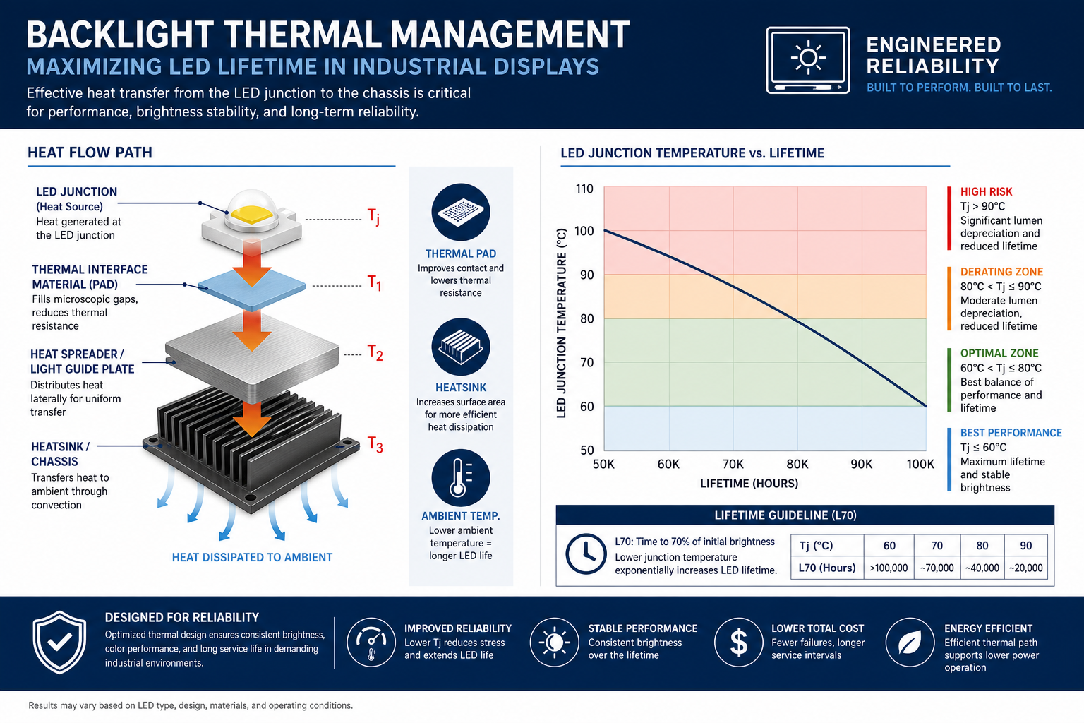
What 50k to 100k hour LED life really means
When a supplier quotes 50,000 or 100,000 hours, that usually refers to a statistical light-maintenance threshold such as L70 or L80 under a defined current and temperature condition. It does not automatically describe full system life in your enclosure. Engineers should ask under what junction temperature, current, and failure criterion the life estimate was derived, whether it references LM-80 style data or an internal acceleration model, and whether the claim accounts only for LEDs or for the driver electronics and interconnects as well.
For a system expected to run 24/7 for seven years or more, it is better to design around life margin than around a marketing number. One practical method is to keep 15 to 25% current headroom after meeting the initial brightness target, then use controlled compensation or conservative default current so brightness decline remains gradual over the field life. In high-brightness outdoor HMI, overdriving LEDs for day-one luminance is rarely the best long-term decision.
| Design variable | Effect on brightness | Effect on lifetime | Engineering guidance |
|---|---|---|---|
| Increase LED current | Strong immediate brightness gain | Raises junction temperature and accelerates lumen depreciation | Do not use alone; pair with thermal and topology improvements |
| Add more LEDs | Improves brightness headroom and often uniformity | Reduces stress per LED and usually improves life | Preferred path in high-brightness industrial designs |
| Improve thermal path | Stabilizes brightness at elevated temperature | Strong positive effect on lumen maintenance and reliability | Higher priority than simply increasing drive current |
| Temperature-based derating | Limits peak luminance in extreme conditions | Substantially improves total system life | Recommended for sealed or outdoor equipment |
Uniformity, hot spots, and optical stack optimization
How uniformity should be specified
Uniformity should not be judged by eye alone. Industrial projects should define a measurement grid, such as 9-point or 13-point luminance mapping, and report min/max or min/average ratio under both room temperature and elevated temperature. HMI users are especially sensitive to uneven brightness on white backgrounds, gray UI themes, and static toolbar regions, so qualification should include real UI imagery at multiple brightness levels.
Where hot spots come from
Hot spots usually arise from too little mixing distance, excessively wide LED pitch, poorly tuned extraction features in the light guide, wrinkled or mis-positioned reflective sheets, frame shadowing, localized thermal loading, or mixed LED bins. Edge-lit systems often show near-edge brightness peaks. Direct-lit systems often reveal emitter signatures. The right fix depends on the root cause: more cavity depth, different diffuser haze, tighter LED pitch, better cavity reflectance, improved frame geometry, or better component matching.
Diffuser, BEF, and polarizer interaction
The optical stack is an interaction problem, not a simple parts list. Diffuser films spread light, soften LED signatures, and improve off-axis appearance. BEF layers increase on-axis luminance by redirecting angular distribution. Reflective polarizers can recover part of the polarization loss in the LCD stack. But these gains do not stack linearly. Too much prism enhancement may raise center-axis nits while sacrificing angular uniformity. Certain film orientations can interact poorly with the top polarizer or touch stack and create rainbow effects, moire, or angle-dependent color shift.
Industrial HMI should usually prioritize consistent readability over laboratory peak luminance. If the product is used in both landscape and portrait orientation, or by multiple operators from different angles, film orientation and viewing-direction bias must be validated in the actual mounting configuration, not just accepted from a standard optical datasheet.
Power budget, efficiency, dimming curves, and flicker-aware design
The backlight is often the largest continuous power consumer in the display subsystem. In battery-powered instruments, PoE terminals, 24 V industrial controllers, and sealed control boxes, backlight power directly affects power-supply sizing, internal temperature, and efficiency compliance.
Building a realistic backlight power budget
A proper budget should include LED electrical power, converter loss, efficiency variation with dimming condition, current variation over temperature, startup surge, and any reserve needed for future brightness compensation. It is useful to maintain separate numbers for typical operating brightness, factory full-brightness mode, high-temperature derated mode, and low-brightness night mode rather than one single maximum wattage number.
Under a fixed luminance target, system efficiency can usually be improved by selecting higher-efficacy LEDs, reducing optical losses, optimizing the LGP and reflective surfaces, reducing driver losses, and keeping LEDs cooler so efficacy remains higher. In environments with large ambient-light swings, automatic brightness control based on an ambient light sensor can significantly reduce average power and extend service life.
Dimming curves should match perception, not just electrical linearity
Human brightness perception is approximately logarithmic, so linearly changing duty cycle or current does not produce linearly perceived brightness. A gamma-corrected or perceptually tuned dimming curve is strongly recommended, especially in the 5% to 30% region where poor tuning makes night operation feel abrupt and inconsistent. At the same time, flicker-aware design means avoiding PWM frequencies that create visible fatigue, camera artifacts, or interaction with optical sensors.
Where cameras, scanners, or machine vision coexist with the HMI, common approaches include moving PWM above the sensor-sensitive range, using hybrid analog-plus-high-frequency PWM control, locking brightness during capture windows, or coordinating backlight behavior with system imaging modes.
Reliability, batch consistency, and field replacement strategy
Why batch consistency matters more in industrial programs
Industrial HMI product lines often ship for five to ten years. Over that time, even if the control board stays stable, changes in LED bins, optical films, LGP vendors, or driver revisions can shift brightness, color temperature, uniformity, and power. For OEM and ODM customers, that affects front-panel consistency, qualification standards, and the ability to service installed equipment without visible mismatch.
That is why supply agreements should define brightness tolerance, color-temperature window, uniformity method, LED binning strategy, end-of-line test criteria, and process for product change notification. For long-life programs, these controls are often more valuable than an impressive one-time prototype result.
Field serviceability and replacement planning
Not every industrial HMI can support field backlight replacement. Fully bonded, sealed, thin modules may require factory-level repair. On the other hand, in high-value equipment where downtime is expensive, the architecture can be planned for replaceable LED bars, separable driver boards, serviceable connectors, and firmware support for lifetime compensation. Either way, the service plan should avoid a repair outcome where the screen is technically functional but visibly mismatched in brightness or color.
For outdoor high-brightness systems, a good spares strategy includes same-batch bar or module stocking, retention of calibration parameters, tracking of operating hours, and luminance/uniformity revalidation after service. Replacing a bar with whatever happens to be electrically compatible is rarely acceptable in industrial equipment.
Industrial TFT LCD backlight FAQ
1. Which is better for industrial HMI: edge-lit or direct-lit?
For small to mid-size modules where thickness matters and brightness stays roughly within 300 to 800 nits, edge-lit is often the better fit. For larger displays, outdoor readability, or targets beyond 1000 nits, direct-lit frequently offers better thermal and brightness headroom. The final choice depends on thickness, power, cost, and uniformity requirements.
2. Can I achieve a high-brightness HMI just by increasing LED current?
You can increase day-one brightness that way, but it is rarely a sound industrial design strategy. Higher current raises junction temperature, accelerates lumen depreciation, and often worsens non-uniformity. A more reliable path is to improve optical efficiency, add emitters, spread heat better, and select LEDs with higher efficacy.
3. What PWM frequency should I use to avoid flicker problems?
There is no universal number. The right value depends on human-visible flicker sensitivity, camera frame and exposure timing, EMI constraints, and driver losses. The practical approach is to choose a sufficiently high frequency, avoid imaging-sensitive bands, and validate with oscilloscope, photodiode, and real camera testing.
4. If the display is specified at 1000 nits, will the finished product also be 1000 nits?
Not necessarily. Bare-module luminance, luminance after adding touch, luminance after cover glass, and stabilized luminance at elevated temperature are all different numbers. The measurement location, optical losses, current condition, and temperature condition must be specified clearly.
5. How should I interpret 50,000-hour vs 100,000-hour backlight life claims?
Those values only make sense together with the underlying test conditions and failure criteria. A higher number measured at lower current and lower junction temperature may not outperform a lower number under harsher and more realistic conditions. For industrial applications, field operating temperature and life margin matter more than a headline life figure.
6. How can I improve backlight uniformity without a large power increase?
Start with the optical path: refine the LGP extraction design, adjust the diffuser stack, improve cavity reflectance, tighten LED bin control, and reduce assembly tolerance variation. Many uniformity problems are optical or mechanical, not electrical.
7. Why does backlight design affect EMI and touch stability?
Boost switching nodes, inductor fields, fast PWM edges, and long LED current loops all generate noise that can couple into touch sensing, display interfaces, or system rails. Driver choice, loop layout, grounding, shielding, and synchronization strategy all matter.
Conclusion: treat the backlight as a system, not a component
Backlight design for industrial TFT LCD and HMI display modules is a system-level balancing act among luminance, thermal performance, lifetime, uniformity, EMI, power budget, and maintainability. The right engineering approach is not to pick a brighter LED or a stronger driver in isolation, but to define readability targets from the use case, build optical and thermal budgets, validate dimming and flicker behavior, and lock the production configuration with clear reliability and consistency controls.
If you are planning a new industrial HMI platform, upgrading to a high-brightness outdoor display, or evaluating thermal margin and driver architecture for a specific module, Senvita's FAE team can support brightness target definition, driver review, thermal path assessment, EMI and flicker validation, and production-consistency planning.