LVDS vs MIPI DSI for Industrial TFT LCD and HMI Display Systems
·Senvita Display Engineering
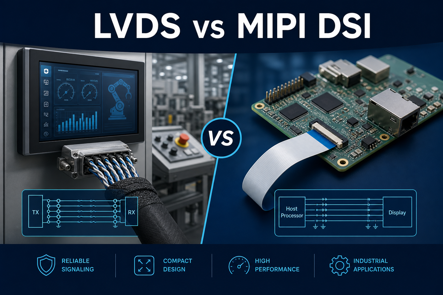
In industrial TFT LCD and HMI display system design, the display interface is not just a bandwidth decision. LVDS and MIPI DSI represent two very different system philosophies. LVDS is rooted in traditional industrial display architecture, emphasizing mid-length interconnects, mature connector ecosystems, and predictable behavior in noisy environments. MIPI DSI comes from the mobile world, where low pin count, compact routing, and high integration are major advantages. For factory HMI panels, medical devices, outdoor kiosks, and embedded ARM platforms, the interface choice directly affects EMI compliance, cable and connector life, production consistency, debug time, and long-term migration cost.
If you are evaluating a new industrial display platform, review the interface together with panel size, host SoC, cable length, enclosure design, and EMC targets. For broader panel selection criteria, see how to choose a TFT LCD for industrial HMI. If your current project already shows emissions, image instability, or flicker symptoms, it is also useful to cross-reference industrial display EMI troubleshooting and industrial display flicker analysis.
Why LVDS vs MIPI DSI still matters in industrial TFT LCD systems
For years, many industrial TFT LCD modules defaulted to LVDS because the connection between the controller board and the display was often more than a short on-board link. Real industrial systems include cable harnesses, interposer boards, locking connectors, metal structures, backlight power stages, and environments with motors, relays, and switching noise. MIPI DSI has become increasingly common as ARM SoCs and high-resolution graphics subsystems spread into industrial equipment, especially in compact HMI, handheld terminals, and Linux or Android-based control platforms.
But industrial conditions are not mobile conditions. Cables are longer, connectors are serviced more often, temperature range is wider, ESD exposure is harsher, EMC margin is tighter, and service life is much longer. That means engineers should not choose an interface only because the processor supports it or because a panel is easy to source. The practical comparison is about link margin, EMC behavior, connector robustness, validation effort, and lifecycle management.
LVDS architecture: differential pairs, 4/8 data lanes, clock pair, and typical 1–2 m cable reach
LVDS, or Low-Voltage Differential Signaling, has stayed relevant in industrial displays because it is a mature differential transport method with relatively strong common-mode noise tolerance and well-understood behavior in board-to-board or module-to-module links. A typical industrial display LVDS interface uses a fixed set of differential data pairs plus a differential clock pair. Common configurations include:
- Single-channel 4 data lanes plus 1 clock pair for mid-range resolutions
- Dual-channel 8 data lanes plus clocking support for higher resolution or higher refresh panels
- Typical industrial cable lengths around 1 to 2 meters when impedance, shielding, and connector quality are controlled
The advantage of LVDS is not only that it can tolerate longer interconnects. It is also easier for industrial engineers to control at the system level. The lane structure is explicit, timing is easier to reason about, and many TFT LCD modules, display control boards, adapter boards, and cable assemblies have been standardized around LVDS. In systems where the display is mounted away from the main board, such as control cabinet doors, articulated operator panels, or medical systems with compartmentalized mechanical layouts, LVDS often fits the architecture more naturally.
How LVDS is typically implemented in industrial HMI
Most industrial LVDS display links include a host processor or display controller, a native LVDS transmitter or serializer stage, a shielded cable or board-to-board connection, and an LVDS receiver on the display timing controller side. In practice, engineers focus on:
- Differential impedance control, commonly targeting 100 ohm differential
- Intra-pair matching and pair-to-pair skew control
- Overall timing relationship between data pairs and the clock pair
- Connector pin assignment, especially separation from backlight power, touch signals, and noisy supplies
- Harness quality, including twist consistency, shielding, and grounding strategy
Because LVDS uses an explicit clock in many implementations, timing debug and margin analysis are relatively transparent. Many industrial teams already know how to validate eye opening, timing margin, and cable substitution behavior, which reduces risk during EVT, DVT, and production ramp.
Where LVDS becomes less attractive
LVDS is not free of tradeoffs. Pin count is significantly higher than MIPI DSI, especially in dual-channel configurations. Connector size and PCB escape routing can become a burden in compact products. As resolution and refresh targets increase, lane count, cable complexity, and BOM cost rise. And if the host SoC does not natively output LVDS, a bridge IC may be required, adding cost, thermal load, and another point of software and power-sequencing dependency.
MIPI DSI: high-speed serial, 1–4 lanes, D-PHY/C-PHY, and lower pin count
MIPI DSI was created for mobile devices, where display bandwidth had to increase while connector and package size had to shrink. A typical DSI configuration uses 1 to 4 high-speed data lanes plus a clock lane. Some platforms also support C-PHY, which uses a three-wire symbol group to improve coding efficiency. In industrial practice, D-PHY remains the most common implementation.
- 1 to 4 high-speed lanes depending on resolution, color depth, and frame rate
- D-PHY as the most common embedded and industrial option
- C-PHY where supported, with higher efficiency but more compatibility checks
- Lower pin count, which helps compact boards, FPC routing, and integrated product design
The major appeal of MIPI DSI is processor integration. Many ARM SoCs and application processors include native DSI output, making it attractive for compact products using small to medium TFT LCD panels. When the distance between the host and the display is very short, DSI can reduce connector footprint, route density, and sometimes total BOM.
Mobile-origin assumptions and industrial tradeoffs
DSI works best when several mobile assumptions are true: the panel is physically close to the processor, the FPC is short and tightly controlled, the connector is precision assembly-grade, and the enclosure creates a stable and predictable environment. Industrial systems often break these assumptions. That introduces additional engineering constraints:
- Greater sensitivity to discontinuities, via transitions, and routing stubs
- Better suited to on-board or very short interconnects than to 1–2 m cable harnesses
- Connector options are often narrower, with more dependence on fine-pitch FPC or BTB styles
- Software bring-up can be more complex because panel init sequences, command timing, and mode settings vary widely
So in industrial use, MIPI DSI is valuable because of integration, low pin count, and ARM compatibility, not because it is a universal replacement for LVDS in every machine architecture.
Industrial comparison: EMI robustness, cable length, connector reliability, temperature, and signal integrity
1. EMI robustness
Both LVDS and MIPI DSI are differential interfaces, but that alone does not guarantee equivalent EMI behavior. LVDS often operates in a more explicit and system-visible link structure, and when paired with shielded twisted cable it can be easier to optimize through grounding, shield termination, and common-mode current management. MIPI DSI has fewer pins, but its high-speed transitions and tighter routing constraints make it more dependent on continuous reference planes, stable return paths, and careful module grounding.
In industrial display design, EMI success is rarely determined by the interface standard alone. Cable length, connector grounding, reference plane integrity, backlight noise, and chassis current paths usually dominate the final EMC result.
If your product is already failing emissions or immunity, the right fix may be system-level rather than a simple interface swap. That is why we recommend reviewing industrial display EMI troubleshooting methods alongside interface selection.
2. Cable length and installation flexibility
LVDS is far more common in industrial systems that need a harness in the 1 to 2 meter range, assuming suitable twisted-pair cable, controlled impedance connectors, and enough timing margin. MIPI DSI is usually best kept on-board, over short FPC, or across a very short board-to-board span. If the LCD is mounted on a cabinet door, boom arm, or separate compartment from the host board, LVDS is generally the safer architecture.
3. Connector reliability
Industrial equipment values insertion life, vibration tolerance, shock resistance, and field serviceability. LVDS more easily maps to locking connectors, shielded cable assemblies, and higher-retention interconnect systems. MIPI DSI often depends on fine-pitch FPC or BTB connectors. Those can work well in compact integrated equipment, but in vibration-heavy or frequently serviced machines they require more mechanical reinforcement and validation.
4. Temperature and long-term stability
Wide-temperature industrial design is not only about the panel. It also depends on the connector system, the cable or FPC material stack, and the available signal margin. At low temperature, FPC stiffness, contact resistance drift, and adhesive behavior can hurt DSI reliability. At high temperature, bridge IC power, SoC heat, and backlight thermal load can reduce timing margin. LVDS often benefits from a longer industrial qualification history for wide-temperature harness and connector assemblies.
5. Signal integrity and debug difficulty
LVDS issues often show up as pair skew, impedance mismatch, grounding faults, cable crosstalk, or clock relationship problems. These are serious but usually straightforward to isolate. MIPI DSI can involve not only hardware SI issues but also protocol state, panel initialization, command mode vs video mode settings, low-power to high-speed transitions, and software timing interactions. For teams using DSI for the first time in an industrial product, bring-up planning should be more conservative.
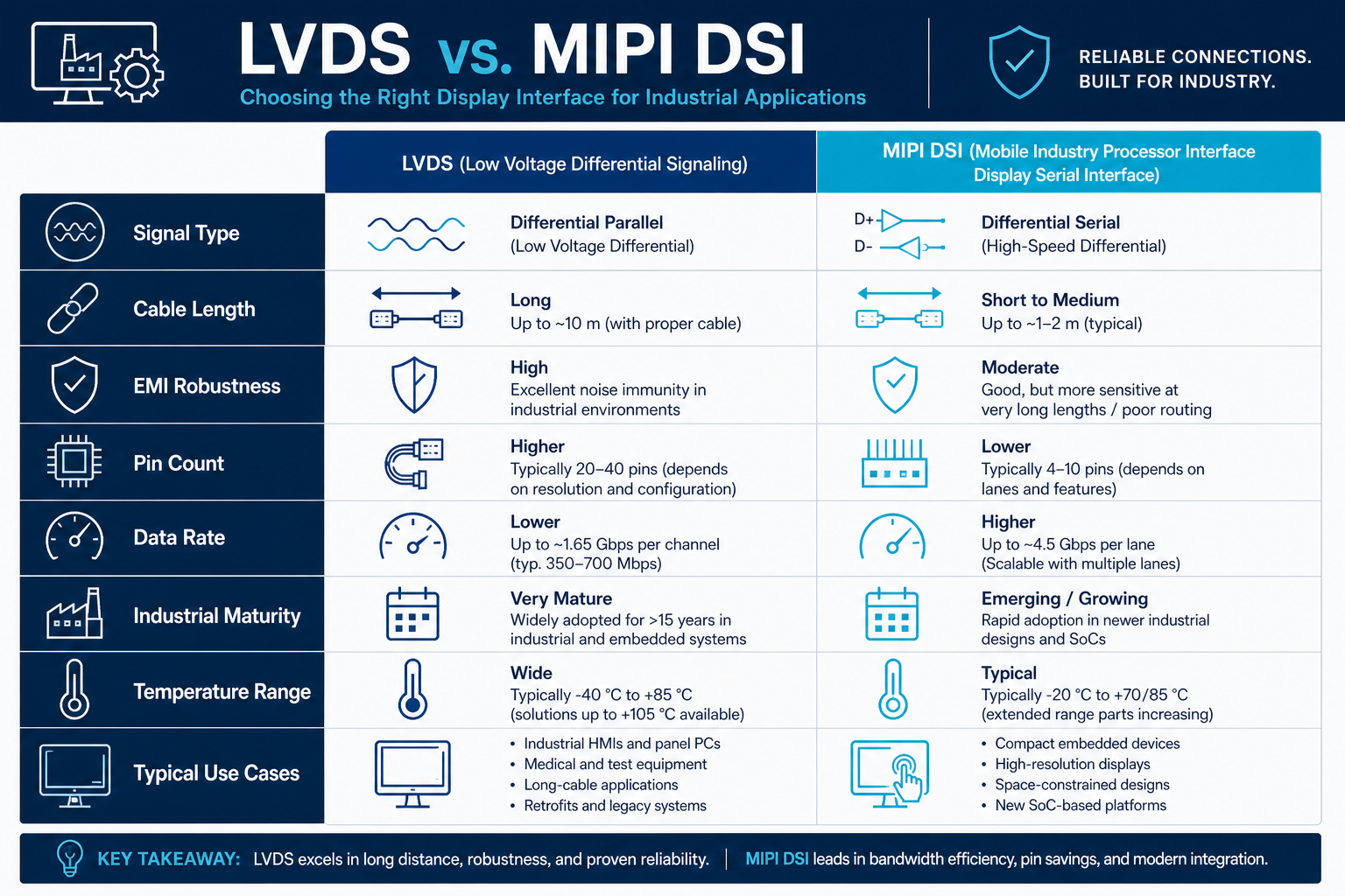
LVDS vs MIPI DSI comparison table for industrial TFT LCD and HMI
| Criteria | LVDS | MIPI DSI |
|---|---|---|
| Typical architecture | 4 or 8 differential data pairs plus clock pair | 1 to 4 high-speed lanes, usually D-PHY; some platforms support C-PHY |
| Pin count | Higher | Lower |
| Typical interconnect reach | About 1–2 m possible in industrial harnesses | Best for on-board or very short links |
| Industrial connector ecosystem | Mature, easy to combine with locking and shielding features | Often fine-pitch FPC/BTB, may need mechanical reinforcement |
| EMI/EMC debug transparency | High, with broad industrial experience | More system-dependent and more tightly coupled to layout and software |
| Native support in ARM SoCs | Sometimes requires bridge IC | Very common |
| Best fit for remote-mounted display | Strong fit | Usually not first choice |
| Best fit for compact integrated product | Possible but bulkier | Excellent fit |
Use-case matrix: factory HMI, medical devices, outdoor kiosk, embedded ARM boards
| Application | Preferred interface | Why | Engineering note |
|---|---|---|---|
| Factory HMI control panel | Usually LVDS | Longer harnesses, strong EMI, serviceable connectors | Use locking connectors, shielded twisted pairs, and defined chassis-ground strategy |
| Medical display subsystem | Depends on mechanical partitioning | LVDS is safer for separated boards; DSI is attractive for tightly integrated designs | Pay extra attention to ESD, leakage paths, aging, and temperature cycling |
| Outdoor kiosk or self-service terminal | Often LVDS | Longer cable paths, wider thermal swings, frequent maintenance | Harden against ESD, surge exposure, shielding failures, and enclosed heat buildup |
| Embedded ARM single-board platform | Usually MIPI DSI | Native SoC support and short display distance reduce size and BOM | Control impedance, secure the FPC, and validate initialization thoroughly |
| Portable industrial handheld | Usually MIPI DSI | Space-constrained, compact board, display close to processor | Validate drop resistance, connector retention, and flex fatigue |
As one practical example, a 7-inch industrial display paired closely to an ARM board is often a good MIPI DSI candidate. If you are benchmarking display module options by size and system integration requirements, you can review the Senvita 7-inch TFT display module as part of your evaluation workflow.
PCB layout, impedance, skew, ESD, and shielding guidelines
LVDS PCB layout checklist
- Maintain consistent differential impedance throughout the route and across connector transitions
- Match line lengths within each pair and manage pair-to-pair skew
- Keep total timing relationship between data pairs and clock pair within transmitter and panel limits
- Preserve a continuous reference plane under the high-speed path and avoid plane splits
- Minimize vias; when layer transitions are required, keep the pair symmetrical
- Separate LVDS from backlight boost converters, motor drivers, relays, and switching power loops
- Reserve optional footprints near the connector for common-mode chokes, ESD devices, and debug access
LVDS harness, shielding, and ESD recommendations
On the cable side, prefer twisted pairs with either overall shielding or grouped shielding depending on the harness architecture. Shield termination requires system thinking. One-end vs both-end shield grounding should be decided based on chassis design, common-mode current behavior, and actual EMC measurements, not by rule of thumb alone. ESD protection belongs close to external connectors, but device capacitance must be checked so that it does not significantly degrade the high-speed channel.
MIPI DSI PCB layout checklist
- Follow the SoC and panel or bridge reference design closely, especially D-PHY constraints
- Keep all lanes as short and direct as possible, with minimal vias and no unnecessary stubs
- Avoid abrupt bends, reference plane interruptions, and blocked return paths around the FPC connector region
- Control lane-to-lane skew and clock relationship more tightly than in casual consumer-style layouts
- Keep high-speed DSI away from backlight PWM traces, touch interrupt lines, and high di/dt power loops
- If a bridge IC is used, verify power-up sequence, reset timing, and strapping behavior from the start
MIPI DSI ESD and mechanical concerns
DSI often reaches the TFT LCD module through an FPC, which means structure and assembly details can become signal-integrity problems. Tight bend radius, poor foam compression, shifted grounding fingers, and under-designed latch retention can all make a lab prototype pass while production units fail intermittently. Use low-capacitance ESD devices rated for high-speed differential links, place them close to the connector entry, and verify their effect on channel quality rather than assuming they are transparent.
Migration considerations from LVDS to MIPI in industrial projects
Industrial teams often evaluate a migration from LVDS to MIPI DSI for three reasons: a new SoC platform, panel supply-chain changes, or a product miniaturization program. The most common mistake is underestimating total system impact. Lighting up a panel is not the same as delivering a reliable industrial display platform.
1. Host and panel compatibility
Confirm lane count, D-PHY or C-PHY support, maximum data rate, command mode vs video mode capability, and the panel driver IC initialization sequence. Compatibility varies significantly across ARM platforms. “Native DSI support” does not automatically mean low-risk integration.
2. Software bring-up and maintenance burden
LVDS issues are often hardware-centric. DSI migration frequently touches device tree settings, kernel drivers, panel timing tables, power sequencing, sleep and wake handling, TE or synchronization behavior, and fault recovery. Because industrial systems live for years, future BSP updates and software support should be included in the decision.
3. Mechanical architecture and cabling redesign
If the existing system depends on a one-meter or longer LVDS harness, a direct replacement with DSI is usually the wrong move. A better architecture is often to keep DSI only for the short host-side link, then convert internally to a more distance-tolerant interface if the display must remain remote. Many failed migrations come from stretching a mobile-oriented interface into an industrial harness use case.
4. Front-load EMC and reliability validation
During migration planning, schedule pre-scan emissions, EFT and ESD sensitivity checks, wide-temperature startup testing, vibration-induced image stability testing, connector reliability after thermal cycling, and simultaneous stress with maximum backlight and active touch. Do not wait until late EVT to discover intermittent DSI unlock caused by enclosure mechanics or FPC strain.
5. Supply chain and second-source strategy
Industrial products often target 5 to 10 years or more of availability. If you move to DSI, assess the continuity of the bridge IC if used, the FPC connector family, the panel driver IC, and the software support resources. LVDS usually offers broader replacement paths, while DSI can be more tightly tied to a specific panel family or processor BSP.
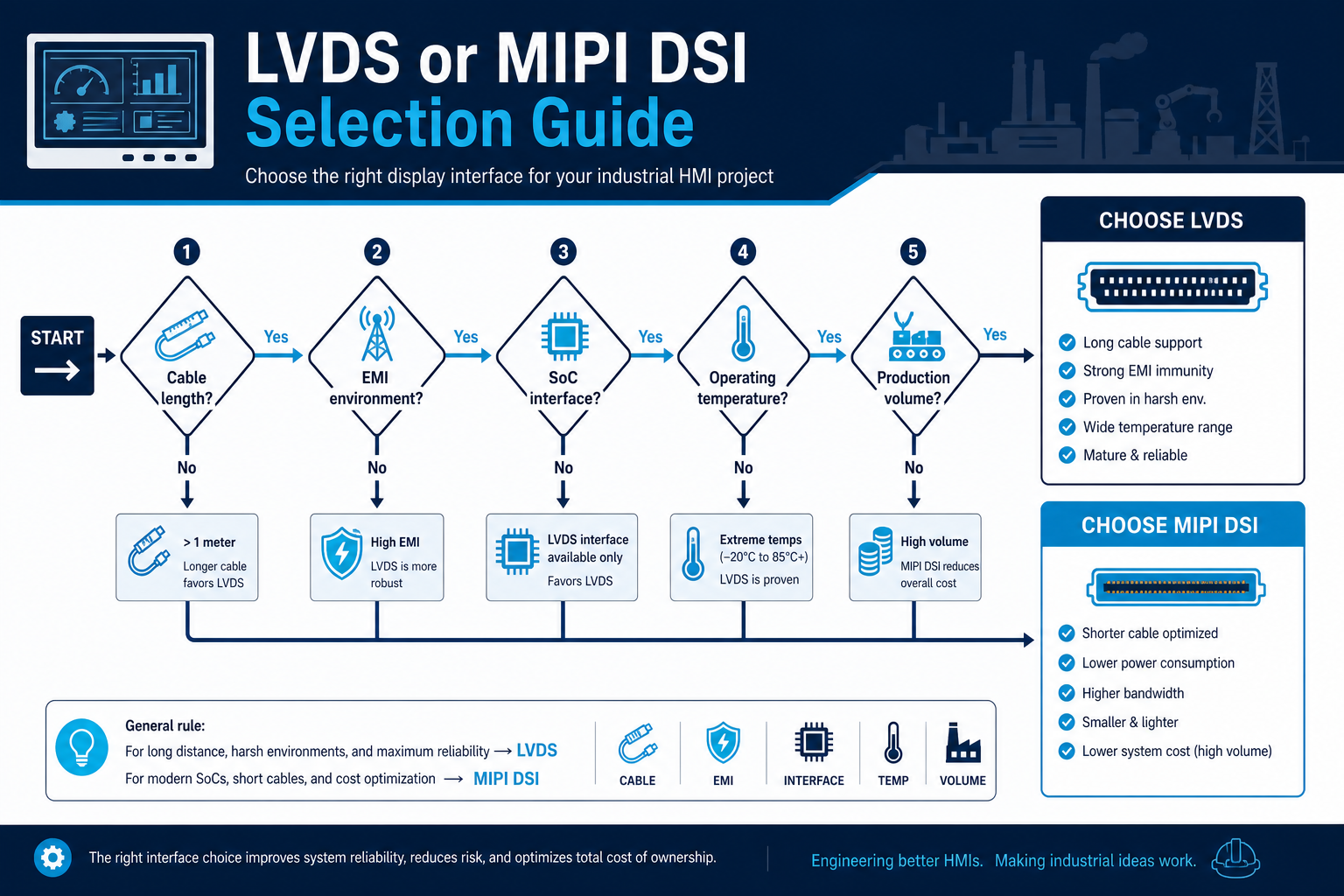
Practical selection logic engineers can use
- If the display is remote from the controller board, the system uses a moderate-length harness, or the environment is noisy and service-heavy, LVDS is usually the stronger choice
- If the product is compact and integrated, the SoC has native DSI, and the display is physically close to the processor, MIPI DSI is usually the better fit
- If schedule risk matters more than theoretical optimization, choose the interface your team can validate and support with confidence
- If the design goal is higher integration rather than longer reach, MIPI DSI usually has the advantage
- If EMC, wide temperature, field maintenance, and connector ruggedness dominate the design, LVDS remains a very practical industrial HMI solution
FAQ: LVDS vs MIPI DSI in industrial TFT LCD and HMI design
Is LVDS always more EMI-robust than MIPI DSI?
No. Both are differential interfaces, and EMI behavior depends heavily on implementation. A short, well-routed DSI link in a compact product can perform very well. A poorly grounded LVDS cable can fail badly. The reason LVDS is often perceived as more robust in industry is that it fits longer cables and rugged connector ecosystems better.
Can MIPI DSI directly replace a 1–2 meter LVDS cable?
In most cases, no. DSI is usually better kept to short interconnects. If you need a remote display, redesign the architecture so DSI stays local to the host or display subassembly rather than extending it across an industrial harness.
If my industrial ARM board has native DSI, should I automatically choose a DSI panel?
Not automatically. Native DSI support can reduce bridge cost, but if the system requires a longer harness, stronger EMC margin, or serviceable locking connectors, LVDS may still be the lower-risk platform decision. System constraints should override processor feature lists.
Is LVDS outdated for high-resolution industrial displays?
No. While many new platforms favor MIPI, LVDS remains relevant across a large number of industrial TFT LCD and HMI systems. The real question is whether the available bandwidth, harness architecture, EMC margin, and lifecycle fit your program requirements.
What should industrial engineers check when choosing D-PHY vs C-PHY?
Start with actual support overlap between the SoC and the panel. Then review driver maturity, tool support, validation capability, and long-term software maintenance. For many industrial teams, D-PHY remains the safer choice because the ecosystem and debug experience are broader.
Which interface is easier from a production and field-service perspective?
If the product involves cable replacement, panel service, repeated insertion, or cabinet-door mounting, LVDS is often easier to support. If the product is a sealed integrated terminal with very short internal interconnects and limited service access, MIPI DSI can be highly efficient.
Conclusion: interface choice should follow system boundaries, not trends
There is no universally superior interface for industrial TFT LCD and HMI display systems. LVDS brings maturity, predictability, 1–2 meter interconnect practicality, and a more rugged industrial connector and harness ecosystem. MIPI DSI brings lower pin count, tighter integration, natural alignment with modern ARM SoCs, and efficient high-density routing over short distances. The right answer comes from evaluating resolution, mechanics, EMC targets, temperature range, production test strategy, and service model together.
If you are planning a new industrial HMI, an ARM-based display controller, or a migration from LVDS to MIPI DSI, Senvita (Shijia Technology) FAE support can help assess interface architecture, signal integrity, EMI risk, harness and connector strategy, and practical TFT LCD module selection for faster and lower-risk development.