
Flicker Analysis for Industrial TFT LCD and HMI Display Systems
Part of: Display Flicker and EMI Troubleshooting Guide
·Senvita Display Engineering
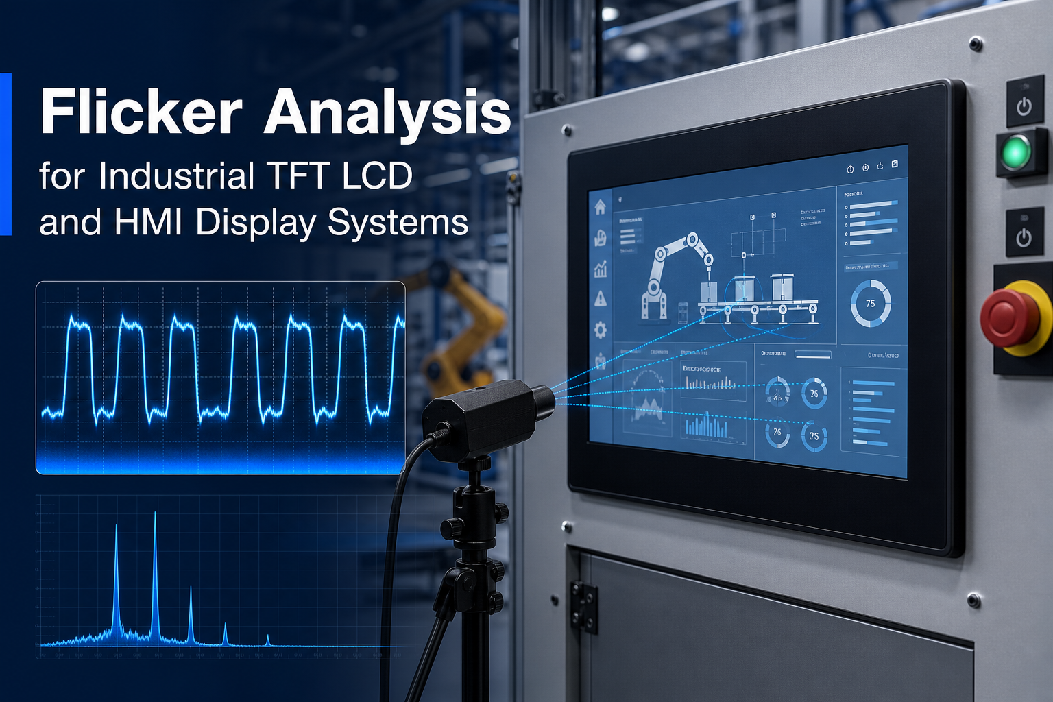
Flicker analysis is a critical part of industrial TFT LCD and HMI display design, especially in factory control panels, medical instruments, embedded operator terminals, and 24/7 equipment where display stability directly affects usability and system trust. In practice, flicker is not limited to obvious visible brightness pulsing. It also includes PWM backlight modulation, beat frequency effects, camera-visible banding caused by refresh mismatch, VFD-induced display instability, LCD response-time artifacts, and stroboscopic perception in dynamic environments. For engineers building industrial display systems, understanding flicker means improving operator comfort, machine-vision compatibility, compliance awareness, and long-term field reliability. This article provides a practical, system-level guide to flicker analysis for industrial TFT LCD modules and HMI display systems, including root causes, metrics, measurement methods, and mitigation strategies.
What flicker analysis means in industrial display systems
In industrial HMI applications, flicker refers to temporal instability in emitted light or perceived image brightness. That instability may be directly visible to the human eye, detectable only under certain dimming conditions, or visible primarily through cameras, scanners, and machine-vision sensors. In real deployments, flicker-related issues often appear as:
- visible low-frequency brightness pulsing at reduced backlight levels;
- rolling bands or dark stripes when the display is photographed or recorded;
- brightness breathing or shimmer during VFD or motor activity;
- motion artifacts that operators describe as unstable, trembling, or flashing graphics;
- fatigue complaints during long shift use on 24/7 factory or medical stations.
That is why flicker analysis should be treated as a system engineering task rather than a panel-only specification review. It spans the LED backlight driver, power integrity, EMC behavior, display timing, optical stack, camera interaction, and field installation conditions.
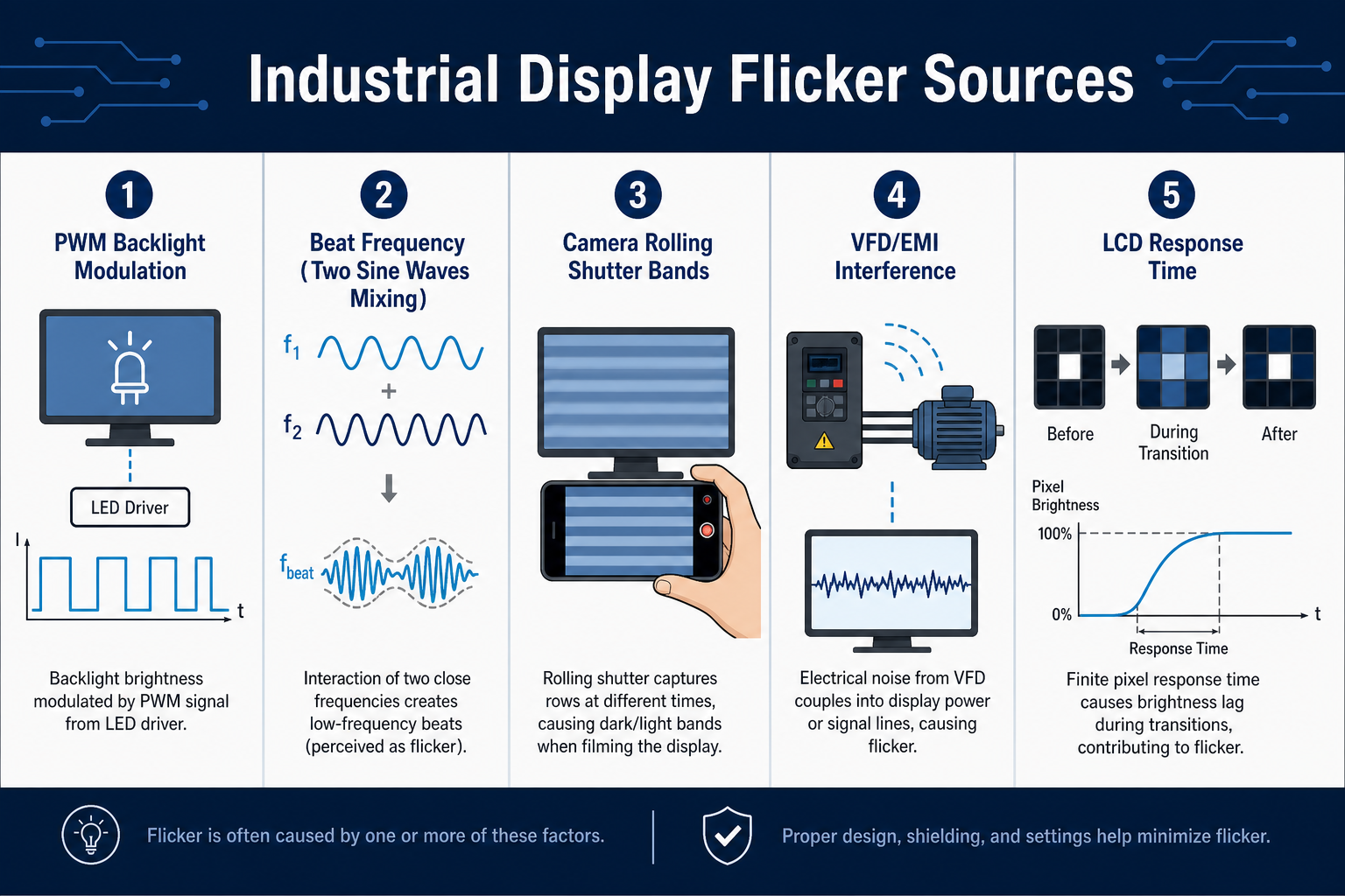
Main sources of flicker in industrial TFT LCD and HMI displays
PWM backlight flicker
The most common source of flicker in industrial TFT LCD modules is the LED backlight dimming method. Many HMI systems use PWM, or pulse-width modulation, to control perceived brightness by varying LED on-time within a fixed period. PWM is attractive because it is efficient, relatively simple to implement, and often preserves LED chromatic behavior better than deep analog current reduction. However, when the PWM frequency is too low, or when the duty cycle becomes very narrow at low brightness, the light output can produce visible flicker, camera banding, and stronger stroboscopic effects.
In industrial use, this problem is amplified because HMI terminals are often operated at low brightness during night shifts, control-room conditions, or battery-backed service modes. A display that appears acceptable at 100% brightness may become problematic at 10% or 5% brightness.
Beat frequency and mixed periodic interactions
Beat frequency occurs when two periodic processes with similar but not identical rates interact, producing a lower-frequency envelope that is much easier to notice. In display systems, common beat interactions include:
- PWM backlight frequency versus camera frame rate or exposure timing;
- display refresh rate versus ambient lighting flicker;
- driver scanning activity versus supply ripple;
- multiple switching regulators interacting with the LED driver.
This is one reason engineers sometimes observe flicker even when the PWM base frequency seems high enough on paper. The user, or the camera, may be seeing the low-frequency difference product rather than the original switching frequency.
Refresh rate versus camera-visible flicker
A human observer and a camera do not sample time in the same way. A 60Hz or 70Hz industrial display may look stable to the eye, yet appear unstable on a smartphone, inspection camera, scanner, or remote maintenance system. Rolling shutter sensors are especially sensitive because they expose the image line by line rather than all at once. If the backlight, frame update, or ambient light changes during that scan, the result can be horizontal bars, moving dark bands, or periodic brightness variation.
This matters more than ever in modern industrial systems because displays are often photographed for remote diagnostics, machine-vision guidance, barcode reading, service records, and digital work instructions. If camera readability is important, engineers should design for both human-visible and camera-visible flicker performance.
VFD-induced flicker and industrial electrical noise
Displays installed near variable frequency drives, servo amplifiers, welders, heaters, and large motor systems can experience flicker that does not originate in the LCD module itself. VFDs generate substantial conducted and radiated noise, including common-mode disturbances and high dV/dt switching edges. If power rails, grounding, shielding, or cable routing are weak, that noise can couple into the display subsystem and modulate the backlight driver, digital video path, or touch controller.
Typical symptoms include intermittent brightness fluctuation, random striping, display shimmer during motor acceleration, or flicker that appears only on the production line and not in a quiet lab. For broader system-level noise troubleshooting, see EMI troubleshooting for industrial displays.
LCD response time and dynamic image instability
LCDs are sample-and-hold devices. Pixel transitions from one gray level to another take finite time, and response speed depends on temperature, gray transition path, drive conditions, and panel design. Slow response does not create backlight flicker by itself, but it can contribute to what users describe as flicker-like instability, especially in fast UI animation, blinking alarm icons, moving trends, or high-speed video capture. When low refresh rate, strong overdrive, and backlight modulation are combined, perceived instability can become worse.
Stroboscopic effect in industrial environments
The stroboscopic effect occurs when periodic light output makes moving objects appear stationary, slowed, segmented, or moving in reverse. In industrial settings, this is not only a comfort issue but a situational awareness issue. An HMI display is not a primary lighting source, but in close-range operator use, low-frequency brightness modulation can still influence perception of rotating machinery graphics, warning indicators, or adjacent moving components. For long-shift operators and safety-sensitive applications, minimizing low-frequency modulation is good engineering practice.
How to evaluate flicker: frequency, modulation, and engineering metrics
Core waveform parameters
Any serious flicker analysis begins with the light waveform itself. Engineers should characterize:
- frequency: the repetition rate of the brightness modulation;
- duty cycle: the on-time ratio in a PWM period;
- modulation depth: how far the light output swings between peak and valley;
- waveform shape: square wave, sinusoidal ripple, burst behavior, or irregular noise;
- low-frequency components: harmonics or envelopes in the range where human sensitivity is higher.
It is a common mistake to look only at nominal PWM frequency. A backlight running above 1kHz can still create objectionable artifacts if the modulation depth is large, if the duty cycle becomes extremely narrow, if supply ripple rides on top of the PWM, or if a beat interaction produces a lower-frequency envelope.
IEEE 1789 and industrial design awareness
IEEE 1789 is often referenced in discussions of LED temporal light modulation and human factors. While it is primarily associated with lighting applications, the conceptual framework is useful for industrial display engineering as well. The practical lesson is straightforward: avoid operating in combinations of low frequency and deep modulation when users are close to the display for extended periods.
For industrial HMI design, IEEE 1789 should be used as a design-awareness and risk-reduction reference, not as the only pass/fail filter. Camera compatibility, EMC environment, operator distance, minimum brightness requirements, and 24/7 duty cycle must also be considered.
Pst and SVM metrics
For more advanced assessment, engineers may use flicker metrics such as Pst (short-term flicker severity) and SVM (stroboscopic visibility measure). These metrics were developed mainly for lighting, but they provide helpful structure when evaluating whether a display backlight may create visual discomfort or motion-related artifacts.
- Pst reflects perceived short-term flicker severity over a defined time interval;
- SVM reflects the visibility of stroboscopic effects on moving objects;
- engineering value: these metrics are particularly useful for medical systems, monitoring stations, inspection equipment, and operator consoles used over long shifts.
| Metric / Parameter | What it describes | Why it matters for industrial HMI | Typical measurement method |
|---|---|---|---|
| Flicker frequency | Repetition rate of light modulation | Determines risk for human perception and camera interaction | Photodiode + oscilloscope FFT |
| Modulation depth | Peak-to-valley light variation | Strongly affects visible flicker and camera banding severity | Time-domain waveform analysis |
| Duty cycle | PWM on-time ratio | Important at low brightness where pulse behavior becomes extreme | Oscilloscope time-domain capture |
| Pst | Short-term perceived flicker severity | Useful for long-duration operator comfort evaluation | Flicker analyzer or software processing |
| SVM | Visibility of stroboscopic effects | Useful in dynamic and motion-related environments | Algorithmic frequency-domain evaluation |
| Camera banding result | Visible outcome of timing mismatch | Critical for service cameras, scanners, and machine vision | Smartphone or industrial camera validation |
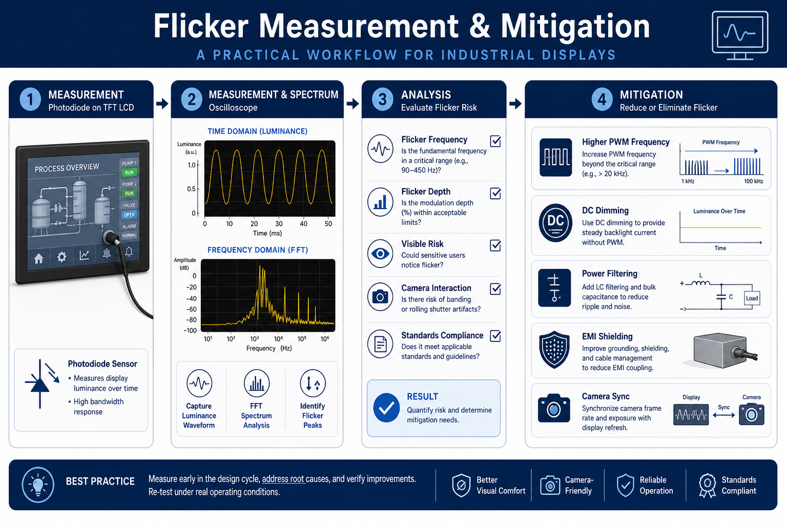
How to measure flicker in industrial display systems
Photodiode plus oscilloscope: the most practical lab method
For industrial TFT LCD backlight evaluation, the most practical engineering method is to capture light output using a fast photodiode or optical sensor and analyze the signal with an oscilloscope. Measuring electrical current alone is not enough; what matters is emitted light. Good test practice includes:
- use a photodiode and amplifier chain with sufficient bandwidth;
- control sensor distance, angle, and ambient light shielding;
- test at 100% brightness, nominal operating brightness, and minimum usable brightness;
- capture both time-domain waveform and FFT spectrum;
- repeat under different input voltages, temperatures, and load states.
In many cases, the minimum brightness state reveals the worst flicker behavior because PWM pulses become narrow and modulation depth becomes more pronounced.
Measure power and control signals at the same time
When root cause matters, correlate optical output with electrical behavior. Useful synchronous channels include:
- LED current waveform or driver output voltage;
- PWM control frequency and duty cycle;
- DC/DC converter ripple;
- 12V or 24V system rail disturbance;
- ground bounce or common-mode noise during VFD activity;
- display timing signals such as VSYNC, HSYNC, DE, or interface activity where relevant.
If optical modulation tracks supply ripple, the issue is likely in the power path. If flicker appears when nearby drives switch states, EMI coupling is the likely suspect. If optical output is relatively stable but cameras still show bars, the problem is usually timing interaction between the camera and the display or backlight modulation.
Camera validation should be part of qualification
Many projects pass electrical review but fail field acceptance because service teams or operators record the HMI with a smartphone and see severe banding. A simple camera validation matrix is worth adding to every industrial display project:
- test with a smartphone, an industrial camera, and any embedded scanner in the product;
- vary frame rate and exposure time where possible;
- test in bright factory lighting, dim control rooms, and low-light night conditions;
- check static pages, alarm pages, gray transitions, and moving trend screens.
| Test item | Recommended tool | What to observe | Typical conclusion |
|---|---|---|---|
| Optical output waveform | Photodiode + oscilloscope | Frequency, modulation depth, beat components | Confirms whether backlight modulation is the main cause |
| LED current waveform | Current probe or sense resistor | Pulse shape, ripple, peak current behavior | Reveals driver topology or filtering weakness |
| Input supply ripple | Oscilloscope with proper probing | 24V/12V disturbance under load events | Identifies power integrity issues |
| EMI field investigation | Near-field probe, spectrum analyzer | VFD switching harmonics and coupling paths | Separates radiated from conducted problems |
| Camera compatibility | Smartphone or industrial camera | Rolling bands, breathing, exposure interaction | Validates real-world usability |
| Pst / SVM evaluation | Flicker analyzer or software algorithm | Comfort severity and stroboscopic visibility | Useful for reports in medical or high-spec projects |
Root-cause workflow for industrial HMI flicker
Step 1: separate backlight problems from image-path problems
If the entire screen brightens and darkens together, the issue usually originates in the backlight, power rail, or system EMI. If only selected gray levels, regions, or animated elements appear unstable, the root cause may involve display timing, TCON behavior, signal integrity, gamma tuning, or LCD response characteristics. During platform selection, it is smart to review module behavior early; see how to choose a TFT LCD for industrial HMI.
Step 2: determine whether brightness setting is the trigger
If flicker is visible only at low brightness, PWM dimming behavior is the leading suspect. If it occurs across the full brightness range, supply ripple, grounding, EMI coupling, or unstable backlight control loops become more likely.
Step 3: correlate the issue with field equipment
Switch nearby VFDs, motors, heaters, or servo systems on and off while monitoring the display. If flicker strongly correlates with a specific machine state, investigate:
- shared 24V rails and transient voltage sag;
- display ground strategy versus chassis ground;
- cable routing between display harnesses and power cables;
- need for common-mode chokes, ferrites, shielding, or LC filtering.
Step 4: determine whether the issue is camera-specific
If humans barely notice anything but cameras show severe banding, the design target should shift from “acceptable to the eye” to “acceptable to both the eye and image sensors.” This is increasingly important in smart manufacturing, telemaintenance, and medical record systems.
Mitigation strategies for flicker in industrial TFT LCD modules
Increase PWM frequency carefully
Raising PWM frequency is one of the most common ways to reduce visible flicker. Moving the main modulation energy higher generally helps human visual comfort and reduces low-frequency camera artifacts. But this is not a one-variable fix. Engineers must also consider:
- driver switching loss and thermal impact;
- possible EMI increase from faster switching edges;
- very narrow pulse behavior at low duty cycle;
- interaction with camera timing and other periodic switching sources.
Use DC dimming or hybrid dimming
For higher-end HMI systems, especially in medical instruments, inspection terminals, and operator stations viewed at close range for long periods, DC dimming or a hybrid strategy may be preferable. A common approach is DC dimming through part of the range, then high-frequency PWM only where necessary. This reduces temporal light modulation but requires careful LED current linearity control, color consistency checks, and driver stability validation.
Improve filtering and power integrity
If the optical instability comes from ripple or industrial noise, changing PWM frequency alone will not solve it. Better results often come from:
- dedicated or better-isolated backlight power rails;
- input LC filtering and stronger local decoupling;
- cleaner DC/DC layout with short current return paths;
- RC conditioning on sensitive control nodes;
- well-defined digital ground, analog ground, and chassis bonding strategy.
Use synchronization when cameras are part of the system
If the product includes a camera, scanner, or machine-vision workflow, synchronization can be a powerful mitigation method. Examples include:
- choosing a PWM frequency that is an integer multiple of the camera frame rate, or far enough away to avoid troublesome beat products;
- defining recommended exposure settings for field service teams;
- providing a dedicated backlight operating mode for photo or video capture;
- enabling a low-banding service mode during machine setup or inspection.
Control EMI, especially near VFDs
For HMIs installed in electrically noisy cabinets or near motor drives, layout and harnessing are as important as display specifications:
- keep display cables physically separated from power wiring;
- use shielded cables with correct grounding practice;
- provide a low-impedance bond between chassis and the display subsystem where appropriate;
- add ferrites, common-mode chokes, and surge suppression where needed;
- perform pre-compliance conducted and radiated checks at the system level.
Select an industrial-grade display module with stable dimming behavior
Module architecture matters. Backlight driver design, optical uniformity, interface robustness, and long-term consistency all affect flicker behavior. For embedded HMI designs, engineers should evaluate industrial-grade modules and integrated support early in the program. A practical reference point is a module such as this 7-inch industrial TFT display, then validate dimming behavior, power interaction, and camera compatibility during prototype testing.
Design considerations for 24/7 industrial and medical equipment
In 24/7 systems, flicker is not only a momentary image-quality problem. It is a long-term reliability and usability concern. Engineering teams should account for:
- aging drift: LED characteristics shift over life, changing current-to-light behavior and low-end dimming performance;
- temperature dependence: backlight driver behavior, boost converter stability, and LCD response time all vary with temperature;
- replacement consistency: spare parts and alternate batches must not introduce new flicker behavior;
- compliance awareness: medical, transportation, inspection, and monitoring systems may require stronger evidence of visual stability and camera readability;
- field diagnostics: serviceable brightness modes and logged dimming parameters can significantly reduce troubleshooting time.
FAQ: common questions about flicker analysis
Why does the HMI look stable to the eye but show strong bands on a phone camera?
This usually happens because the camera samples the display differently from the human eye. Rolling shutter exposure interacts with PWM backlight modulation or frame refresh timing, creating visible bars even when the screen appears stable in person.
Is higher PWM frequency always better?
No. Higher frequency often helps, but not automatically. Thermal impact, switching loss, EMI, low-duty-cycle pulse behavior, and beat interaction with cameras must all be considered. A well-optimized dimming architecture is better than a single headline frequency number.
Does DC dimming completely eliminate flicker?
Not necessarily. DC dimming greatly reduces periodic light modulation, but ripple, unstable current regulation, and external electrical noise can still modulate light output. LED color shift and low-current linearity also need validation.
What should we check first if flicker appears only near a VFD or servo drive?
Start with shared power rails, grounding topology, cable routing, shielding, and backlight filtering. Many field flicker complaints are integration issues rather than defects in the LCD panel itself.
Can slow LCD response time be mistaken for flicker?
Yes. In moving graphics, scrolling text, blinking alarms, or high-speed camera capture, slow response can cause unstable-looking transitions, ghosting, and incomplete gray changes that users describe as flicker.
Do industrial HMIs need Pst and SVM testing?
Not every project requires it, but it is highly valuable for medical equipment, long-duration operator consoles, monitoring stations, and systems where visual comfort or motion-related perception matters.
How can we reduce flicker risk during module selection?
Validate dimming behavior, minimum brightness performance, camera compatibility, EMI robustness, and power ripple sensitivity during the prototype stage. Choosing an industrial-grade TFT module and working closely with experienced application engineers can prevent costly redesigns.
Conclusion
Flicker analysis in industrial TFT LCD and HMI display systems is broader than a simple brightness complaint. It includes PWM backlight modulation, beat frequency, camera-visible artifacts, refresh interaction, VFD-induced noise, LCD response limits, and stroboscopic risk. A reliable design approach combines optical measurement with a photodiode and oscilloscope, electrical correlation, camera validation, and mitigation across dimming strategy, power design, EMI control, synchronization, and module selection.
If you are evaluating an industrial HMI display, troubleshooting low-brightness flicker, or dealing with camera banding and VFD-related instability in the field, Senvita (Shijia Technology) FAE support can help accelerate root-cause analysis and recommend production-ready display, driver, and integration optimizations.