
Industrial TFT LCD Connector Pinout Guide
Part of: Display Subsystem Architecture for HMI
·Senvita Display Engineering
Connector pinout work is usually invisible when it is correct and very expensive when it is wrong. Industrial TFT LCD assemblies combine power rails, high-speed data, backlight control, touch signaling, and often auxiliary detect lines in one harness, so a single mapping mistake can stop the whole system. A field-oriented reference for harness planning is available here: industrial connector pinout and cabling.
Definition
A pinout defines the function, voltage domain, direction, and polarity of each connector contact. For display modules, that usually includes supply pins, ground return paths, differential or parallel video signals, backlight enable and dimming, touch data, and presence detect. The pinout must be treated as a contract between mechanical, electrical, and firmware teams.
- Document every pin with signal name, voltage level, tolerance, and failure consequence.
- Separate high-current backlight return paths from sensitive data returns wherever possible.
- Mark keyed orientation, insertion direction, and cable retention explicitly in the drawing set.
Problem: A panel powers up but shows no image.
Cause: The harness is pinned correctly for power but incorrectly for data lanes, or the differential pair polarity was mirrored during assembly.
Solution: Verify the pin map against the connector drawing, then check lane ordering and polarity end to end before replacing the panel.
Problem: The backlight flickers when the cable is moved.
Cause: The backlight enable or PWM line is sharing an unstable return path, or the connector has poor contact pressure on a control pin.
Solution: Rework grounding, separate noisy control lines from power delivery, and use retention hardware that prevents intermittent contact.
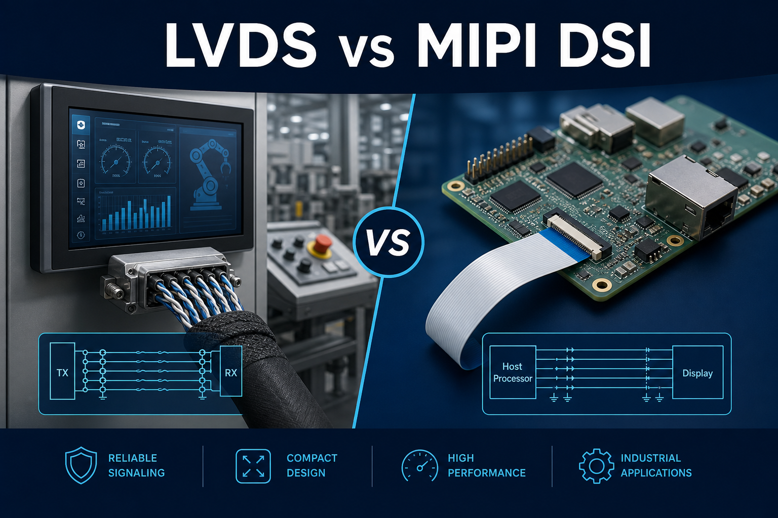
Interface choice affects the pinout as well, especially with serialized video. See LVDS vs MIPI Industrial Display and EMI Troubleshooting Industrial Display for the electrical tradeoffs that follow from the connector definition.
Validation
Validation should start with continuity and end with system stress. A clean schematic is not proof that the harness is correct.
- Run a pin-to-pin continuity audit from PCB header to panel end.
- Measure contact resistance, especially on high-current backlight and ground pins.
- Shake and flex the cable while monitoring video stability and touch event integrity.
- Confirm that connector keying prevents mis-insertion during service work.
Related engineering notes: Touch Controller Integration in Industrial HMI, MCU vs FPGA Display Interface Architecture, EDID and EEPROM Configuration for Display Modules.