
Thermal Management for LCD Modules
Part of: High-Brightness TFT LCD Engineering
·Senvita Display Engineering
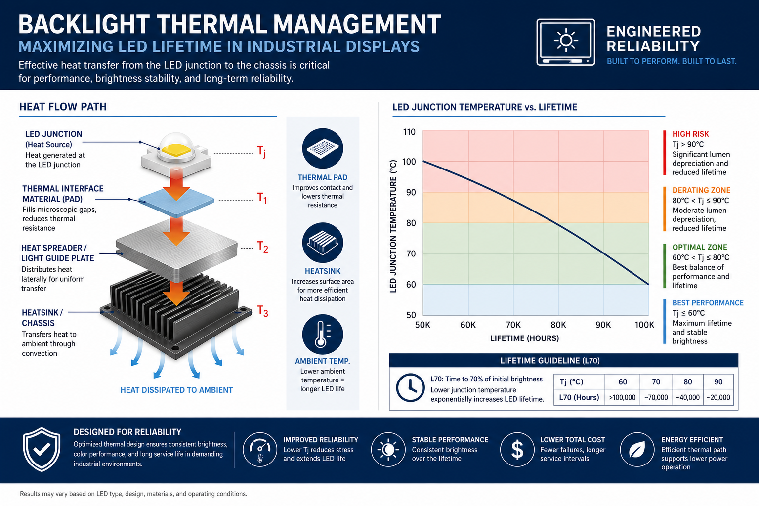
Thermal management for LCD modules is the process of keeping the display stack within safe operating limits while maintaining visual performance. For industrial HMIs, temperature affects LED efficiency, liquid crystal response, adhesive aging, and driver reliability, so thermal design is directly tied to display quality.
Definition
An LCD module generates heat in the LED backlight, the power conversion stage, and sometimes the surrounding control electronics. That heat must move out through conduction, convection, and radiation. If the path is poor, the module may still function but lose brightness, shift color, or age prematurely.
- Measure hot spots on the LED strip, driver ICs, and local PCB copper.
- Model the full enclosure, not only the display assembly.
- Set brightness targets based on hot-state performance.
- Reserve margin for dust buildup, clogged vents, and ambient drift.
Problem: The display meets brightness targets on the bench but fails after enclosure integration.
Cause: The thermal environment changes once the module is boxed in and airflow is restricted.
Solution: Validate the module in the final housing and set derating rules for the real system.
Problem: Backlight brightness drops after long operation even when the driver is still active.
Cause: LED junction temperature rises, reducing luminous efficiency and accelerating aging.
Solution: Improve heat spreading from the LED zone and lower steady-state thermal resistance.
Problem: The display shows color shift or uneven brightness at high ambient temperature.
Cause: Temperature gradients across the panel and optical stack are too large.
Solution: Balance heat sources, improve mechanical coupling, and avoid local hot spots near the optics.
Engineering actions that usually matter most:
- Provide a low-resistance path from the backlight and regulators to the enclosure.
- Use thermal pads or metal interfaces only where they do not stress the panel.
- Keep cable and connector placement away from high-temperature zones.
- Define brightness derating curves tied to measured internal temperature.
Related brightness and system tradeoffs are covered in High-Brightness TFT LCD Engineering. Thermal impact on readability is linked to Sunlight-Readable Display Engineering and to Wide-Temperature Reliability Testing for Industrial Displays.
For external power-path context, see DC-DC converters for displays.
Validation
- Run thermal soak at minimum and maximum ambient temperatures with the display fully lit.
- Measure luminance drop, color shift, and driver temperature over time.
- Check hot spots with IR imaging or thermocouples at the LED and power stages.
- Verify that derating behavior is deterministic and documented for production use.
Thermal design is complete only when the display remains within brightness and reliability limits in the final enclosure, not just on the workbench.