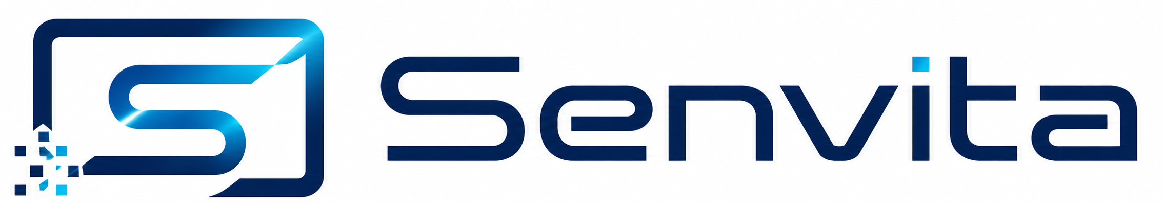
EMI Troubleshooting for Industrial Display Systems
Part of: Display Flicker and EMI Troubleshooting Guide
·Senvita Display Engineering
Electromagnetic interference (EMI) is one of the most common root causes of unstable industrial display behavior—yet it is often misdiagnosed as a defective LCD module, cable, or touch controller.
This engineering guide explains how to systematically troubleshoot EMI in industrial TFT LCD, LVDS, and MIPI DSI display systems. It covers symptom identification, source isolation, mitigation design, and validation—so your HMI remains stable in real factory, energy, and automation environments.
What Is EMI Troubleshooting in Industrial Display Systems?
EMI troubleshooting is the structured process of identifying, isolating, and eliminating electromagnetic noise that degrades display signal integrity, power stability, or touch performance. In industrial HMI projects, EMI troubleshooting typically focuses on:
- Display video links (LVDS / MIPI / RGB)
- Backlight driver and PWM control circuits
- Touch controller I2C / SPI communication
- Chassis grounding and cable coupling paths
Key principle: EMI is a system-level problem. Replacing the LCD alone rarely fixes recurring flicker or intermittent blank screens if the noise source and coupling path remain.
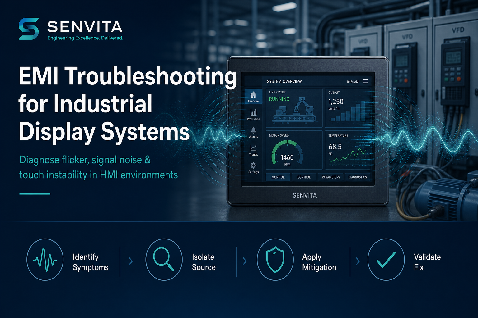
1. Common EMI Symptoms in Industrial LCD Systems
Before changing hardware, map symptoms to likely coupling mechanisms:
| Symptom | Likely EMI Mechanism | Typical Trigger |
|---|---|---|
| Display flicker | Conducted noise on power or ground | VFD startup, relay switching, motor drive PWM |
| Image noise / snow | Radiated coupling into LVDS/MIPI pairs | Long unshielded cables near switching power |
| Touch instability | Ground potential shift + controller noise | Chassis ground loops, poor PE connection |
| Intermittent blank screen | Signal integrity margin loss | High dV/dt events, connector vibration, cold temperature |
| Horizontal banding | Beat frequency between backlight PWM and system clock | Shared power rail, inadequate filtering |
2. Primary EMI Sources in Industrial Environments
Industrial plants introduce EMI through both conducted and radiated paths:
2.1 Conducted EMI Sources
- Variable Frequency Drives (VFDs) and servo inverters
- DC/DC and switching-mode power supplies (SMPS)
- Relay and contactor coil collapse (inductive kickback)
- Shared ground return paths with high di/dt loads
2.2 Radiated EMI Sources
- Motor cables and long unfiltered power lines
- Arc welding equipment and plasma cutters
- Wireless RF systems in close proximity
- Poorly shielded high-speed switching nodes
Displays are victims in most cases—the noise enters through cables, connectors, apertures, and grounding architecture rather than originating inside the panel.
3. Step-by-Step EMI Troubleshooting Workflow
Use this field-proven sequence to avoid random part swapping:
Step 1 — Reproduce and Document
- Record exact trigger events (motor start, VFD ramp, door open, temperature)
- Capture video of flicker and log timestamps against machine state
- Note interface type (LVDS / MIPI), cable length, and connector type
Step 2 — Isolate the Victim Path
- Test display on bench supply away from machine noise
- Swap only the display cable first—keep panel and controller fixed
- Disable touch temporarily to separate video vs. touch EMI paths
Step 3 — Scan Power and Ground
- Measure ripple on LCD VDD and backlight supply under load
- Check chassis-to-PE continuity and star-ground reference integrity
- Look for ground loops between PLC, display, and metal enclosure
Step 4 — Apply Targeted Mitigation
- Add ferrite clamps on LVDS/MIPI cables near noise sources
- Route display cables away from VFD output and motor leads
- Improve shield termination (360° contact, not pigtail-only)
Step 5 — Validate Under Stress
- Re-test during worst-case machine cycles—not only idle bench conditions
- Run temperature and vibration stress if deployed in field cabinets
- Confirm BER / eye margin for MIPI links before production release
4. LVDS vs MIPI: EMI Sensitivity in Practice
| Factor | LVDS | MIPI DSI |
|---|---|---|
| Typical industrial robustness | High — mature differential signaling | Moderate — layout-dependent |
| EMI margin at longer cable runs | Generally better up to ~1 m with proper cable | Degrades faster with impedance mismatch |
| Common failure signature | Snow, color shift, line instability | Cold-start artifacts, lane deskew errors |
| Troubleshooting priority | Cable shield + ground reference | PCB length matching + connector integrity |
For electrically noisy cabinets, LVDS industrial TFT modules such as the STK070 HDFLD092 (7.0″, 1024×600) remain a reliable default. See also our guide: How to Choose the Right TFT LCD for Industrial HMI.
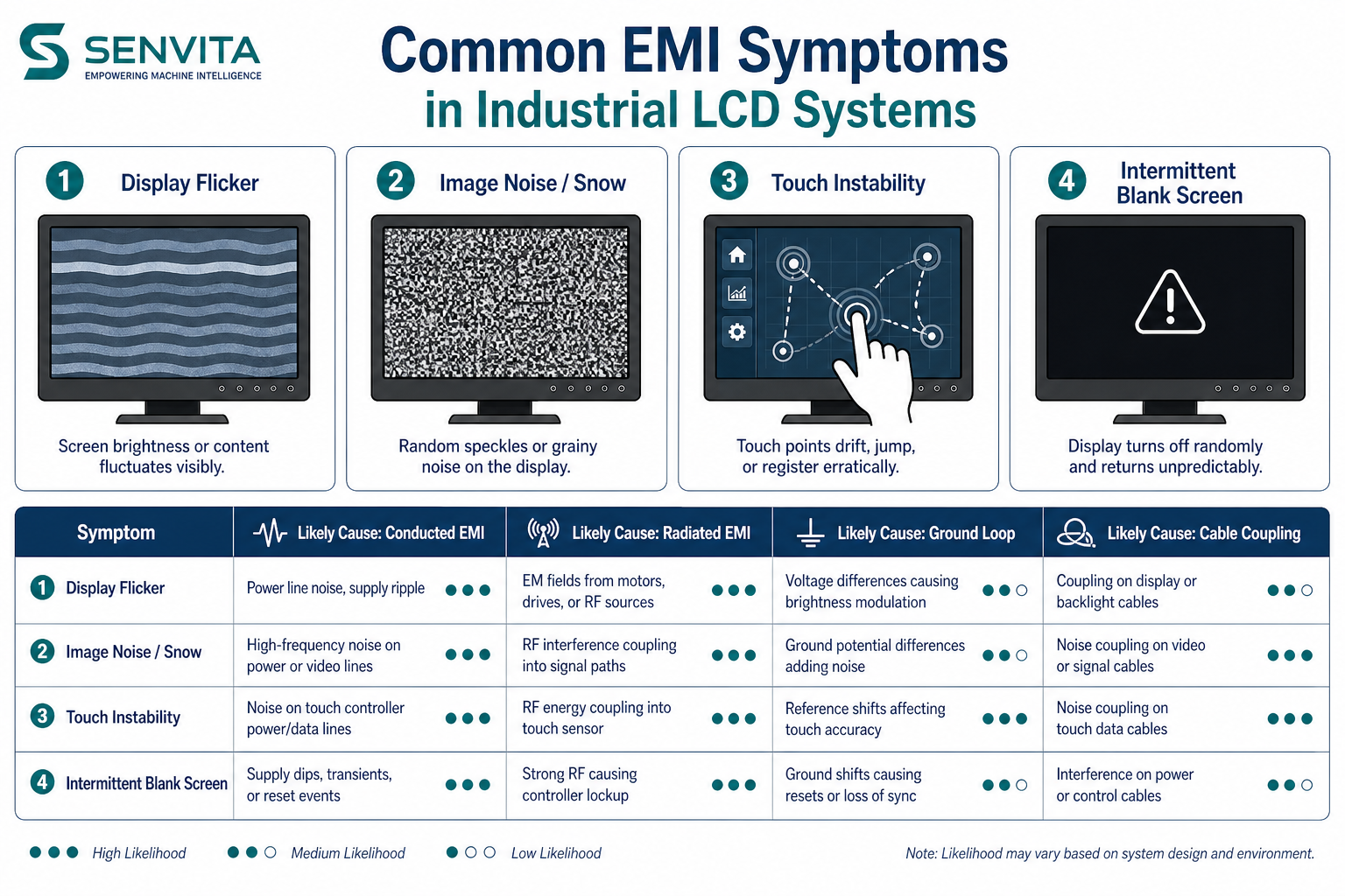
5. EMI Mitigation Best Practices
Effective mitigation combines grounding discipline, shielding, and routing—not a single component swap.
5.1 Grounding Architecture
- Use a single reference ground for display logic, chassis, and shield drains
- Avoid routing signal return current through painted or anodized mounting surfaces
- Terminate cable shields at the connector backshell with 360° contact
5.2 Shielding and Filtering
- Specify industrial-grade shielded LVDS/MIPI cables with defined impedance (100 Ω differential typical)
- Add ferrite components on cables entering the display enclosure
- Filter backlight PWM inputs and ADC references if beat-frequency banding appears
5.3 PCB and Cable Routing
- Keep high-speed display pairs away from SMPS inductors and relay drivers
- Match differential pair length and avoid sharp vias on MIPI escape regions
- Separate power and signal harnesses in the cabinet wireway
6. Display Module Selection for EMI-Heavy Applications
When EMI cannot be fully eliminated at the system level, module selection matters:
Recommended for noisy industrial HMI cabinets:
- STK070 HDFLD092 — 7.0″ LVDS, 1024×600, up to 1600 nits
- Industrial connector options and validated wide-temperature operation
- Engineering support for custom cable length, brightness, and bonding stack
7. Frequently Asked Questions (FAQ)
Why does my industrial display flicker only when the VFD starts?
VFDs inject conducted harmonics and ground potential shifts during acceleration. Display flicker at startup usually indicates shared ground return or inadequate filtering on the LCD/backlight supply—not a defective panel by default.
Is display flicker always caused by a bad LCD module?
No. In field service data, a significant share of "LCD defects" are traced to cable routing, grounding, or power ripple. Always complete system-level EMI troubleshooting before RMA.
Does LVDS resist EMI better than MIPI?
In most industrial cabinets, yes. LVDS differential signaling and mature cable practices provide higher margin. MIPI can work well but requires stricter PCB layout and shorter, controlled interconnects.
Can ferrite beads fix all EMI display issues?
Ferrites help suppress high-frequency cable radiation but do not replace proper grounding, shield termination, or power filter design. Use them as part of a system solution.
How do I test whether touch or video is affected by EMI?
Disable touch in firmware or disconnect the touch FPC while reproducing the fault. If video remains unstable, focus on LVDS/MIPI and power. If video is clean but touch fails, inspect I2C reference and chassis ground loops.
What documentation should I prepare before contacting FAE support?
Provide interface type, cable length/drawing, power schematic, photos of routing, trigger video, and machine electrical single-line diagram. This accelerates root-cause analysis significantly.
8. Engineering Support from Senvita
If EMI symptoms persist after systematic troubleshooting, Senvita FAE teams can support:
- Display interface and cable architecture review
- LVDS / MIPI integration validation
- Custom module and bonding stack recommendations
- Pre-production EMC risk assessment for HMI deployments
Request EMI troubleshooting support or engineering consultation →
Conclusion
EMI troubleshooting for industrial display systems requires methodical reproduction, path isolation, and system-level mitigation—not guesswork. Teams that treat flicker, noise, and touch instability as EMI problems first reduce false RMA rates, shorten commissioning time, and improve long-term HMI reliability in demanding environments.