Wide Temperature Guide for Industrial TFT LCD and HMI Display Systems
Part of: Industrial TFT LCD Selection Guide
·Senvita Display Engineering
In industrial HMI, outdoor control equipment, energy systems, cold-chain terminals, transportation displays, and high-heat machinery, display failures are rarely caused by resolution alone. More often, the root cause is poor temperature definition, insufficient derating, or incomplete validation. A wide temperature TFT LCD design is not a single panel specification; it is a system problem involving the LCD cell, backlight, driver ICs, touch stack, adhesives, connectors, housing materials, and the thermal behavior of the full product. This guide explains how industrial TFT LCD and HMI display systems behave across temperature extremes and how engineers can design for reliable startup, readability, touch performance, and field life.
If you are still at the platform selection stage, first align your application requirements with the display architecture in our guide to choosing TFT LCD for industrial HMI. For thermal symptoms that appear as flicker, unstable startup, or noisy touch behavior, it is also useful to cross-reference our articles on EMI troubleshooting in industrial displays and display flicker analysis, since temperature extremes often amplify power integrity, timing, and signal integrity weaknesses.
Operating temperature ranges for industrial TFT LCD and HMI display systems
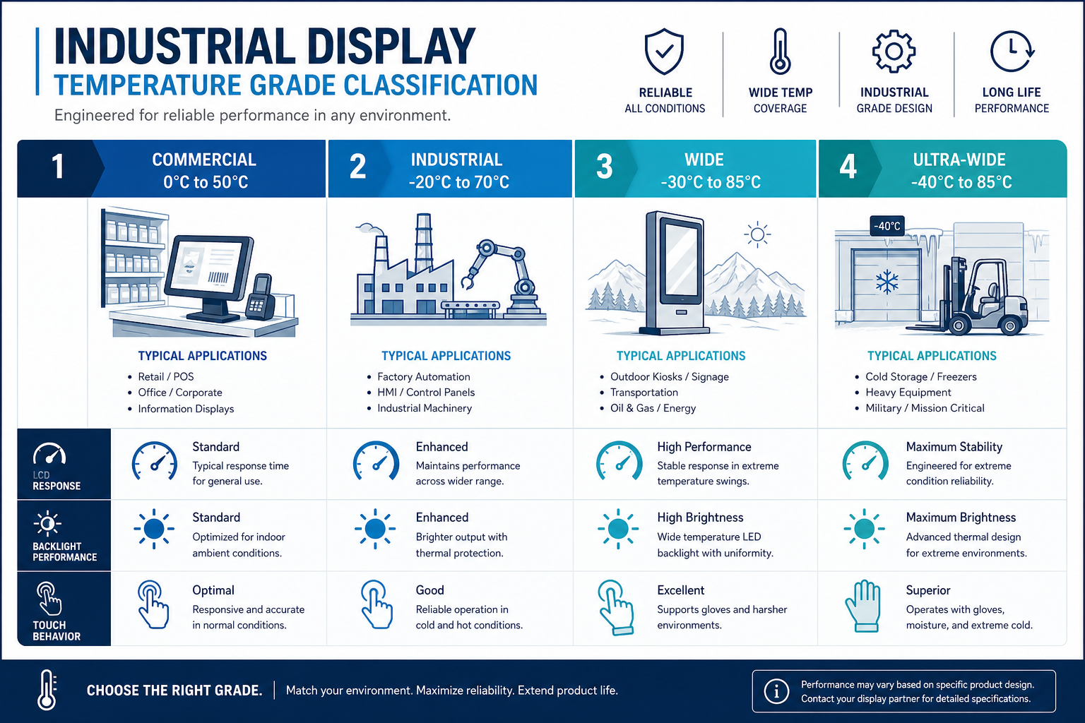
Terms such as commercial, industrial, wide temperature, and ultra-wide temperature are useful shorthand, but they are not complete engineering definitions. In practice, engineers must distinguish between panel operating temperature, module operating temperature, system operating temperature, storage temperature, and whether cold power-on is required at the minimum limit. A TFT LCD that looks fine at 25°C is not automatically readable at -30°C, and a module that can function at +85°C is not guaranteed to maintain brightness, color stability, or backlight life under continuous exposure.
| Temperature class | Typical operating range | Common applications | Primary engineering concern |
|---|---|---|---|
| Commercial | 0~50°C | Indoor terminals, consumer products | Cost optimized; limited margin for cold response and hot life |
| Industrial | -20~70°C | Indoor industrial HMI, factory automation | More stable LC mix, better backlight derating, broader component screening |
| Wide temperature | -30~85°C | Outdoor cabinets, energy equipment, cold-chain, transport devices | Cold start, thermal cycling, condensation, and touch drift become critical |
| Ultra-wide temperature | -40~85°C | Severe outdoor cold, specialty vehicles, extreme industrial environments | Highest demand on system thermal design, preheat strategy, materials, and validation |
These ranges should be treated as targets, not assumptions of uniform performance. For robust product definition, the engineering specification should separate:
- Power-on capable range versus normal readable range.
- Whether startup is required directly at the minimum ambient temperature, such as -40°C cold power-on.
- Acceptable brightness, contrast, response time, color shift, and touch sensitivity degradation at the range limits.
- Backlight lifetime expectations at elevated internal temperatures, not just ambient temperatures.
- Real enclosure hotspot temperature, especially in sealed systems where PMICs, CPUs, LED drivers, and power modules raise local temperature above ambient.
How liquid crystal behavior changes with temperature
The core limitation of a TFT LCD at temperature extremes comes from the liquid crystal material itself. The electro-optic response depends on molecular reorientation under an electric field, and temperature strongly affects viscosity, elastic constants, birefringence behavior, and recovery speed. In practical terms, low temperatures slow response dramatically and can reduce usable contrast, while high temperatures speed response but shift optical behavior and accelerate material aging elsewhere in the display stack.
Low temperature effects: slower response, more smear, reduced readability
As temperature drops below 0°C and deeper into -20°C, -30°C, or -40°C regions, liquid crystal viscosity rises. Molecules move more slowly, and transitions between gray levels take longer. This creates several familiar field symptoms:
- Visible image smear and ghosting in scrolling text, waveform displays, machine status animation, and camera feeds.
- Reduced effective contrast or compressed gray scale, especially before the panel has warmed internally.
- Cold startup delay in which the display is technically on but not yet comfortably readable.
- More obvious uniformity or gamma-related artifacts if timing and bias conditions are not well matched to the panel’s low-temperature behavior.
High temperature effects: faster response does not mean lower risk
At elevated temperature, liquid crystal response usually becomes faster because viscosity falls. However, that improvement does not eliminate risk. Optical parameters shift, black state performance may degrade, contrast may drop, and color balance can move. More importantly, the rest of the display system suffers accelerated aging: LED backlights, polarizers, adhesives, and driver components all lose life faster at high temperature. A display that still looks acceptable at +85°C in a short test may still have a poor long-term field life if internal hotspots remain high.
| Temperature change | Physical LCD behavior | Visible system effect | Engineering response |
|---|---|---|---|
| Below 0°C | Higher LC viscosity, slower response | Smear, lag, gray shift | Use wide temp LC formulations, reduce low-temp motion demands, define preheat behavior |
| -30 to -40°C | Severely limited molecular mobility | Slow cold start, temporarily unreadable image | Validate cold startup time; consider heaters or controlled warm-up |
| +70 to +85°C | Faster response, optical drift | Contrast reduction, black level rise, color shift | Improve thermal path, manage bias and enclosure hotspots |
| Long-term high temperature | Accelerated material aging | Brightness loss, yellowing, non-uniformity | LED derating, material screening, corrected life modeling |
A common engineering mistake is to treat the operating range as a constant-performance range. For industrial TFT LCD systems, it is better to define separate limits for power-on capability, readable performance, full-spec performance, and allowable recovery time at the extremes.
Backlight derating in wide temperature design
Many wide temperature display projects fail first in the backlight rather than in the LCD cell. LED luminous efficiency, forward voltage, chromaticity, and lifetime all depend on temperature. At low temperature, LED forward voltage rises and startup margin becomes tighter. At high temperature, luminous efficiency falls, junction temperature rises, and life degrades faster. The LED driver IC also has its own operating and junction temperature constraints. If the boost converter, inductor, switching device, or current regulation path has insufficient thermal margin, the result can be dim startup, flicker, thermal foldback, intermittent shutdown, or permanent failure.
Cold-end backlight concerns
- LED forward voltage increases at low temperature, so the driver must retain enough output voltage headroom.
- Boost startup performance at -30°C or -40°C must be chamber-validated, not assumed from room temperature behavior.
- Diffusers, light guides, and reflective films can shift dimensionally with temperature and affect luminance uniformity.
Hot-end backlight concerns
- Higher LED junction temperature reduces brightness and shifts color point.
- Driver ICs, inductors, capacitors, and switching devices must all be rated for internal hotspot temperature, not ambient alone.
- Outdoor high-brightness systems must include solar load in the thermal budget, otherwise enclosure temperature assumptions will be wrong.
In production designs, it is usually better to derate backlight current than to run continuously at the module’s maximum nominal current. If target brightness is met at 100% current in the lab, a more robust field design may run at 70% to 85%, preserving margin for thermal drift, lot variation, and lifetime requirements. When more brightness is required, a better solution is often improved optical efficiency, higher-efficiency LEDs, or a stronger thermal path rather than simply increasing current.
| Backlight element | Low-temp risk | High-temp risk | Recommended action |
|---|---|---|---|
| LED source | Higher Vf, startup difficulty | Higher junction temp, brightness loss, shorter life | Provide driver margin, derate by junction temperature, model lifetime |
| LED driver IC | Unstable cold startup | Thermal shutdown, current drift | Validate extreme startup and monitor hotspot temperature |
| Light guide / diffuser | Uniformity shift from dimensional change | Warping, aging, yellowing | Select temperature-stable materials and validate with cycling |
| Connector / cable | Contact resistance variation | Reduced insulation margin and life | Use industrial-rated parts with retention features |
If you are evaluating actual module options, compare brightness, interface, and industrial environmental capability together. For example, a candidate such as the Senvita 7-inch industrial TFT display module should be assessed as a full stack, including panel, backlight, touch, and mechanical integration under the target temperature profile, not as a panel-only specification.
Touch performance in wide temperature environments
In modern HMI systems, display readability and touch usability must both survive the same environment. Many projects pass LCD temperature testing but fail at the touch layer: poor sensitivity in winter gloves, baseline drift at thermal extremes, higher noise in high temperature or humidity, or edge-zone instability after repeated thermal cycling. Capacitive touch performance is especially sensitive to stackup geometry, grounding, controller tuning, and moisture behavior.
Typical CTP issues across temperature
- Temperature shifts the sensor baseline capacitance, and weak baseline tracking can cause false detection or reduced sensitivity.
- Low-temperature use often coincides with thicker gloves, reducing effective coupling and making standard settings inadequate.
- High temperature and humidity can worsen leakage, EMI coupling, and grounding weakness, producing jitter or ghost touches.
- Thermal expansion mismatch among cover lens, sensor, adhesive, and housing can redistribute stress and degrade local touch performance.
Engineering actions for wide temperature touch
If the HMI must be used in cold storage, outdoor winter conditions, or by operators wearing gloves, the touch strategy must explicitly define glove mode, water rejection, baseline tracking, noise suppression, and acceptance criteria for the actual glove materials used in the field. Tuning should be performed on the final stackup, not on an early bare-sensor lab build. Since touch stability is tightly linked to grounding and conducted/radiated noise, chamber tests should be paired with EMI observation. Our industrial display EMI troubleshooting article is useful when thermal extremes appear to “create” touch problems that are actually noise-margin problems.
Glove mode should not be treated as a simple gain increase. Aggressive sensitivity settings often reduce water immunity and make the interface more vulnerable to noise and condensation. A more robust approach is co-optimization across controller firmware, cover thickness, sensor routing, grounding, shielding, and system power quality.
Storage temperature vs operating temperature, thermal cycling, and condensation
Most industrial display specifications list both operating temperature and storage temperature, but these two ratings serve different purposes. Operating temperature defines the range in which the powered system is expected to function within stated limits. Storage temperature defines what the product can withstand while unpowered during transport or warehousing. Engineers must not assume they are interchangeable. A display may be storable at -40°C without being capable of immediate -40°C power-on with usable image quality.
Thermal cycling is more than a min/max check
Field failures are often driven not by steady-state hot or cold conditions, but by repeated transitions. Thermal cycling creates cumulative stress because the display stack contains glass, metal, films, adhesives, plastics, and connectors with different coefficients of thermal expansion. Common cycling-related failure mechanisms include:
- Polarizer and glass stress mismatch leading to curl, edge distortion, or optical change.
- OCA, tape, and seal materials becoming brittle in cold and soft in heat, gradually losing adhesion.
- FPC traces, solder joints, and connector interfaces accumulating fatigue damage.
- Cover lens and housing stress coupling into the touch sensor and shifting local sensitivity.
Condensation can be more dangerous than absolute temperature
When an HMI moves from cold conditions into warm humid air, or when an enclosure experiences strong day-night swings, condensation can cause more practical trouble than the temperature limit itself. Moisture can fog the viewing surface, trigger false touches, increase leakage, corrode terminals, and lower insulation resistance over time. Cold-chain, outdoor, and high-humidity industrial systems should evaluate dew point, venting, sealing, membrane strategy, and any active heating logic. A rated -30~85°C operating range does not automatically solve condensation risk.
If a product may be powered after low-temperature storage, the specification should define the recovery condition or permissible power-on condition. Otherwise, condensation-related faults are frequently misdiagnosed as LCD or touch hardware defects.
Validation methodology: chamber testing, -40°C power-on, soak profiles, and MTBF impact
Temperature validation for industrial TFT LCD and HMI display systems must be more precise than a simple datasheet check. A good plan separates component-level, module-level, and system-level validation, while recording readability, startup time, backlight behavior, current draw, touch function, interface stability, and structural effects together. Merely confirming that “an image appears” in a chamber is not sufficient for a production-grade wide temperature design.
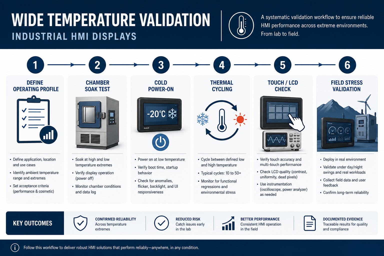
Recommended validation items
- Room temperature baseline: establish brightness, contrast, color point, touch sensitivity, power draw, and startup behavior at 25°C.
- Cold soak plus direct startup: for example, soak at -40°C for 2 to 4 hours, then power on and record first light, readable time, and touch recovery.
- Hot soak plus continuous operation: for example, +85°C operation while tracking brightness drop, current, color drift, and any thermal protection behavior.
- Thermal step and cycling: cycle repeatedly between low and high temperature and inspect adhesive interfaces, connectors, touch edge zones, and mechanical distortion.
- Condensation scenario testing: move from cold to humid environments and observe fogging, touch false events, leakage, and recovery time.
| Validation item | Example condition | Primary metrics | Recommendation |
|---|---|---|---|
| Cold startup | Power-on after -40°C soak for 2 to 4 h | First light, readable time, touch availability | Define maximum allowed startup time and temporary degradation window |
| Low-temp operation | Continuous run at -30°C or -40°C | Smear, gray response, flicker, current | Use real UI motion and not only static images |
| High-temp operation | Continuous run at +70°C or +85°C | Brightness, color shift, backlight stability, thermal shutdown | Measure internal hotspots and driver temperatures |
| Thermal cycling | Multiple -40 to +85°C cycles | Adhesion, warpage, contact stability | Re-test function and appearance after cycling |
| Storage testing | Unpowered high/low temperature exposure | Recovery behavior, appearance, delamination | Define whether return-to-room condition is required before power-on |
Why -40°C power-on must be specified separately
In ultra-wide temperature projects, customers often state that the display must “support -40°C.” Engineers should immediately ask what that means: storage, operation after stabilization, or direct cold power-on. These are very different requirements. Direct power-on at -40°C stresses not only the LCD cell but also the backlight driver, DC/DC startup path, oscillator behavior, reset thresholds, touch controller initialization, and software timing. Many failures that look like display issues are actually power architecture weaknesses revealed by temperature.
Temperature and MTBF
Higher temperature accelerates failure mechanisms across many components, including LEDs, driver ICs, PMICs, connector springs, films, and adhesives. Even when a display remains operational at +85°C, long-term MTBF may still drop sharply. That is why life assessment should not rely on room-temperature data alone. Backlight lumen maintenance, component junction temperature, and adhesive aging should be modeled using actual hotspot conditions and duty cycle assumptions, then tied into the system reliability plan.
Material selection for wide temperature industrial displays
Material choice often determines whether an industrial TFT LCD design can scale from prototype to reliable production. Early builds made with consumer-grade films, tapes, or stackup materials may look fine at room temperature and fail only once chamber testing begins. Typical symptoms include bubbles, yellowing, edge lift, touch drift, connector instability, and optical non-uniformity.
Polarizer and optical film selection
Polarizers can shrink, warp, change transmission, or yellow under heat and humidity. Under repeated thermal cycling, they can also develop stress mismatch relative to glass and surrounding layers. In outdoor or high-duty industrial HMI, the polarizer system should be checked not only for temperature capability but also for long-term UV and thermal load compatibility.
Adhesives: OCA, PSA tape, and seal materials
Adhesives are frequent hidden failure points in wide temperature designs. Engineers should verify:
- That glass-to-sensor and sensor-to-LCD OCA systems truly cover the target operating and storage range.
- Whether the adhesive becomes brittle at low temperature or creeps and flows at high temperature.
- How humidity affects adhesion, insulation, and optical clarity.
- Whether long-term cycling creates bubbles, whitening, edge lift, or delamination.
Connectors, FPC, and harness materials
Wide temperature interconnect design requires more than low initial contact resistance. Review plating, contact metallurgy, lock style, housing polymer temperature rating, FPC bend behavior, and low-temperature brittleness. In vibration plus thermal cycling environments, locking connectors and controlled strain relief are strongly preferred.
Housing and mechanical frame
The enclosure and front frame directly affect display reliability because their stiffness, thermal expansion, and conductivity shape both heat flow and stress transfer. Metal housings may improve thermal spreading but can transmit more mechanical stress to the glass stack if not isolated. Plastic housings require attention to high-temperature deformation and low-temperature cracking. Uneven clamping often causes local light leakage, edge touch problems, or abnormal glass stress after cycling.
Wide temperature design checklist for industrial HMI teams
The most effective way to manage wide temperature risk is to define it early, before EVT or DVT reveals expensive problems. The checklist below can be incorporated directly into product reviews:
- Define ambient temperature, internal hotspot temperature, solar load, and mounting constraints.
- Separate storage, operation, cold startup, hot restart, and recovery conditions.
- Confirm the shared temperature boundary across LCD, backlight, touch, drivers, connectors, and adhesives instead of reviewing panel data alone.
- Match low-temperature readability requirements to the application: static digits, machine UI, waveforms, and video have different limits.
- Set high-temperature brightness derating and lifetime targets explicitly.
- Validate power architecture cold-start capability, especially DC/DC converters, clocks, and reset chains.
- Include EMI, flicker, and touch-noise checks in thermal validation since these issues often interact.
- Create a separate condensation and environment-transition test plan for outdoor and cold-chain products.
If you are still defining platform requirements, use this guide alongside our industrial HMI TFT LCD selection article. If the issue appears later as flicker, unstable startup, or thermal touch drift, our flicker analysis guide and EMI troubleshooting guide can help narrow the root cause more efficiently.
FAQ: wide temperature industrial TFT LCD and HMI design
1. If a TFT LCD is rated -30~85°C, does that mean performance is constant across the full range?
No. The rating usually means the module can operate within defined limits, but brightness, contrast, response time, color, smear, and touch behavior can still vary significantly with temperature. Engineers should specify acceptable degradation and startup delay at the limits rather than assuming full performance everywhere.
2. If storage temperature is -40°C, does that mean the display supports direct power-on at -40°C?
No. Storage rating only describes unpowered survivability. Direct power-on at -40°C is a cold-start requirement and must be validated separately across the LCD, backlight driver, power supply, clocks, touch controller, and system firmware. In many cases the limiting factor is the power path, not the LCD cell itself.
3. If low-temperature smear is severe, is panel replacement the only fix?
Not always. First determine whether the issue is a fundamental LC response limit or an application mismatch. Review the UI motion profile, timing configuration, gamma behavior, and whether a warm-up period is acceptable. Some applications can improve usability through UI changes or startup logic, while more demanding systems may indeed require a different wide temperature panel technology.
4. Is brightness drop at high temperature always a failure?
No. Some brightness drop is expected because LED efficiency falls with temperature. However, if the drop exceeds plan, check LED current, junction temperature, thermal path, driver thermal foldback, and optical material stability. High-temperature brightness behavior should always be reviewed together with lifetime expectations.
5. Why does capacitive touch often struggle in winter glove use?
Gloves reduce capacitive coupling, and low temperature can add baseline drift and different noise behavior. Reliable glove operation requires coordinated design across cover lens thickness, sensor layout, grounding, controller tuning, glove mode parameters, and system EMI management. Raising gain alone often increases false touches and reduces water immunity.
6. If the product passes thermal cycling, does that guarantee no condensation issues in the field?
No. Thermal cycling mainly checks mechanical and functional stability under temperature transitions. Condensation depends on humidity, dew point, sealing, venting, and airflow. Outdoor, cold-chain, and high-humidity products need separate transition testing that includes moisture effects.
7. What components are most often overlooked in wide temperature display design?
Commonly overlooked items include the LED driver IC, connector housing polymers, OCA and pressure-sensitive tapes, touch controller initialization conditions, and localized enclosure hotspots. Teams often focus on panel temperature class while the first real limit is reached elsewhere in the stack.
Conclusion
Wide temperature design for industrial TFT LCD and HMI display systems is ultimately about managing system boundaries. It is not enough to know that a module can light up at a certain temperature. Engineers need to know whether it can cold-start, how long it takes to become readable, how backlight current should be derated, whether touch remains stable with gloves or condensation, and whether materials will survive cycling without hidden life loss. Only when LCD physics, backlight thermal design, touch tuning, material selection, and environmental validation are treated as one engineering problem does a wide temperature specification become meaningful in the field.
If you are defining a -20~70°C, -30~85°C, or -40~85°C industrial display platform, Senvita’s FAE team can support module selection, wide temperature risk review, validation planning, and joint optimization of touch and backlight behavior to help turn a temperature requirement into a production-ready HMI solution.