LVDS, MIPI, or RGB: Choosing the Right Display Interface
Part of: Industrial TFT LCD Selection Guide
·Senvita Display Engineering
Display interface selection should be driven by the electrical path, not only by the panel datasheet. In industrial HMIs, the right interface depends on cable length, controller support, resolution, refresh rate, EMI margin, and whether the display is integrated into a local board or a remote module.
For upstream semiconductor and reference-design context, see the shijiaic.com Engineering Hub article on TFT interface selection reference.
Definition and selection boundary
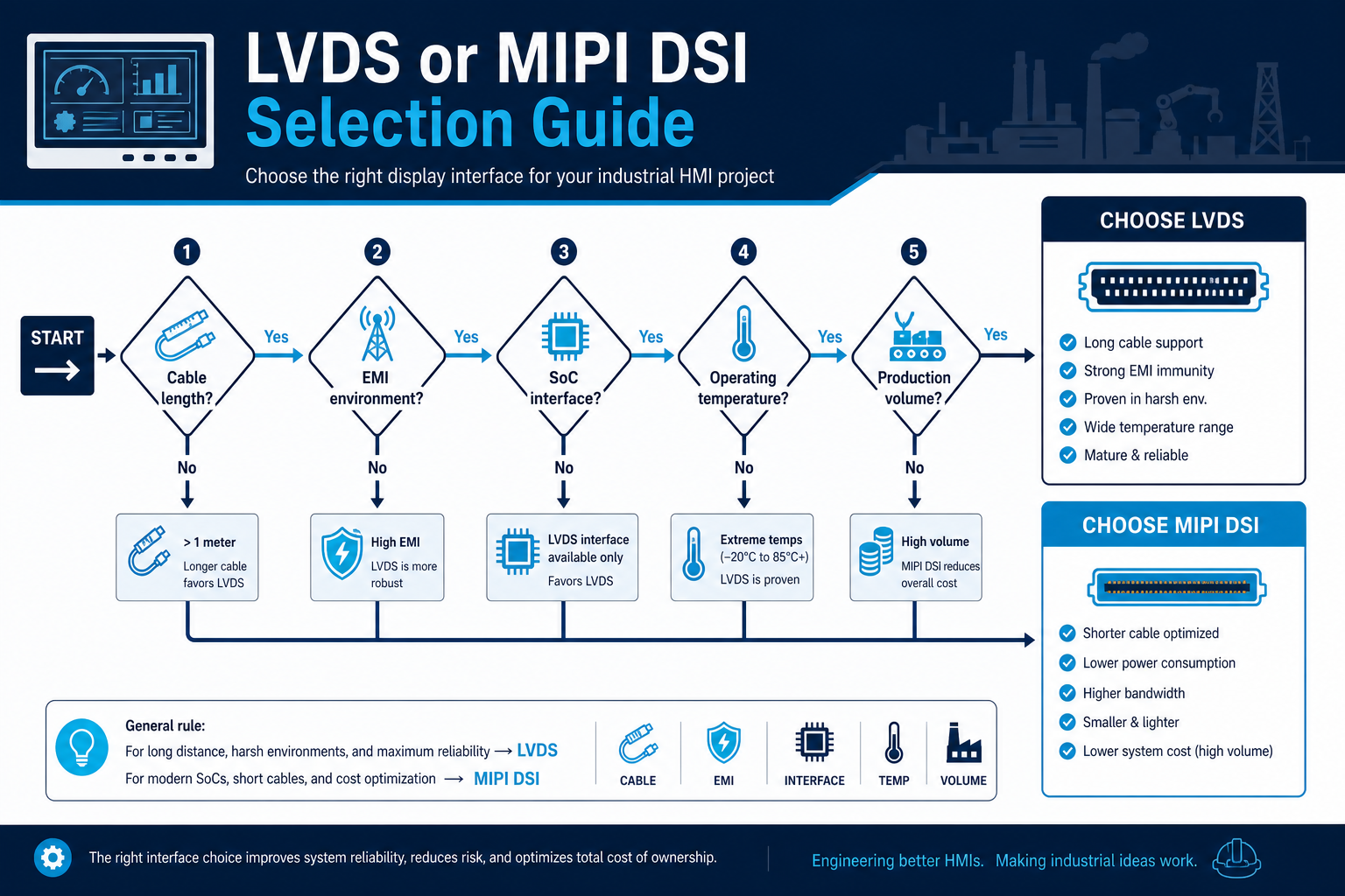
LVDS, MIPI DSI, and RGB all move pixel data, but they assume different system architectures. LVDS is tolerant of longer runs and is common in embedded industrial modules. MIPI DSI is efficient on short, tightly controlled paths. RGB is simple in concept but requires careful timing, many signals, and good board routing.
- Use LVDS when the cable path is longer or the environment is noisy.
- Use MIPI when the controller and display are close and lane count must be minimized.
- Use RGB when the platform already exposes a parallel interface and the resolution is moderate.
- Do not choose by bandwidth alone; connector count, EMI, and driver availability matter equally.
Cause: Differential lanes were treated as a cable interface even though the link budget and skew tolerance were not designed for that distance.
Solution: Shorten the path, add a bridge device, or switch to an interface intended for the actual mechanical separation.
Cause: The parallel bus uses many traces, making skew, crosstalk, and return-path issues harder to control.
Solution: Review timing margins, reduce trace mismatch, or move to a serialized interface with fewer conductors.
Cause: The SoC, timing controller, and power-up sequence were not checked as a set.
Solution: Validate the full display subsystem early, including timing, reset sequencing, and link training.
Interface selection is tightly connected to system architecture. A good starting point is the Display Subsystem Architecture for HMI, followed by a direct comparison of LVDS vs MIPI for Industrial Displays and the practical steps in EMI Troubleshooting for Industrial Displays.
Validation
Validation should be done on the full wiring path, not only with a known-good demo cable. Confirm signal integrity, power sequencing, and image stability under vibration, temperature variation, and cabinet noise.
- Check eye margin or at least scope the waveform at the connector.
- Verify lane mapping, polarity, and pin assignment before board spin.
- Measure start-up sequence timing across cold and hot conditions.
- Run EMI pre-scan while the display is active at full refresh.
Once the electrical path is proven, return to the Industrial TFT LCD Selection Guide to confirm the interface fits the overall display plan.