
How to Select Brightness for Industrial Displays
Part of: Industrial TFT LCD Selection Guide
·Senvita Display Engineering
Brightness selection for an industrial TFT LCD is a system decision, not a standalone panel spec. The usable target depends on ambient light, cover-glass reflection, optical bonding loss, LED aging, thermal margin, and how the HMI is mounted in the machine.
Definition and selection boundary
In module data sheets, brightness usually means luminance at the front surface in cd/m². For engineering selection, define three values: nominal brightness at shipment, minimum brightness after warm-up and aging, and the brightness that still meets readability in the worst ambient condition.
- Indoor control room: 300–500 cd/m² is often enough if reflection is controlled.
- Factory floor with mixed light: 500–800 cd/m² is a practical starting point.
- Near windows or outdoor kiosks: 1000 cd/m² or higher is often required.
- High brightness does not replace low reflectance; a glossy stack can fail even at 1500 cd/m².
Cause: Ambient light reduces contrast and the cover glass adds reflection.
Solution: Recalculate contrast in the installed stack, reduce reflection, and raise luminance only after optical loss is quantified.
Cause: LED current is set without thermal derating, and the enclosure traps heat behind the backlight.
Solution: Set a case-temperature limit, model LED junction temperature, and define a derating curve instead of using one fixed current.
Cause: PWM frequency is too low, or the dimming scheme switches between analog and PWM regions without a clean boundary.
Solution: Specify a minimum PWM frequency, verify low-brightness behavior with a photodiode, and check the dimming transfer curve under real load.
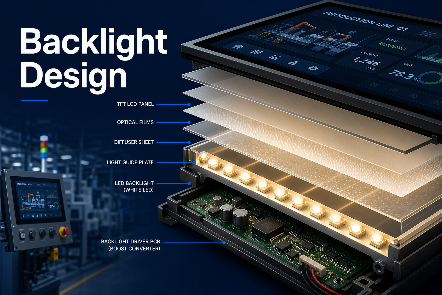
Brightness must also be selected together with the backlight architecture, because the LED string count, driver current, and optical stack loss determine the true system-level value. See the related engineering notes on Backlight Design for Industrial TFT LCDs, High-Brightness TFT LCD Engineering, and Flicker Analysis for Industrial Displays.
Validation
Validate brightness with the module in its final mechanical stack, not with the bare panel alone. Measure luminance after warm-up, at the minimum and maximum ambient light expected in the field, and again after thermal soak. Use the same cover glass, gasket, and bonding method that will ship.
- Measure center and corner luminance to detect backlight non-uniformity.
- Check readability at the actual viewing distance and installation angle.
- Repeat the test after thermal cycling to catch LED and diffuser drift.
- Confirm that dimming does not introduce visible flicker or color shift.
For selection work, link the brightness target back to the overall decision flow in the Industrial TFT LCD Selection Guide. A brightness number without an environmental assumption is not actionable.