Random Line Artifact Troubleshooting for HMI Displays
Part of: Display Flicker and EMI Troubleshooting Guide
·Senvita Display Engineering
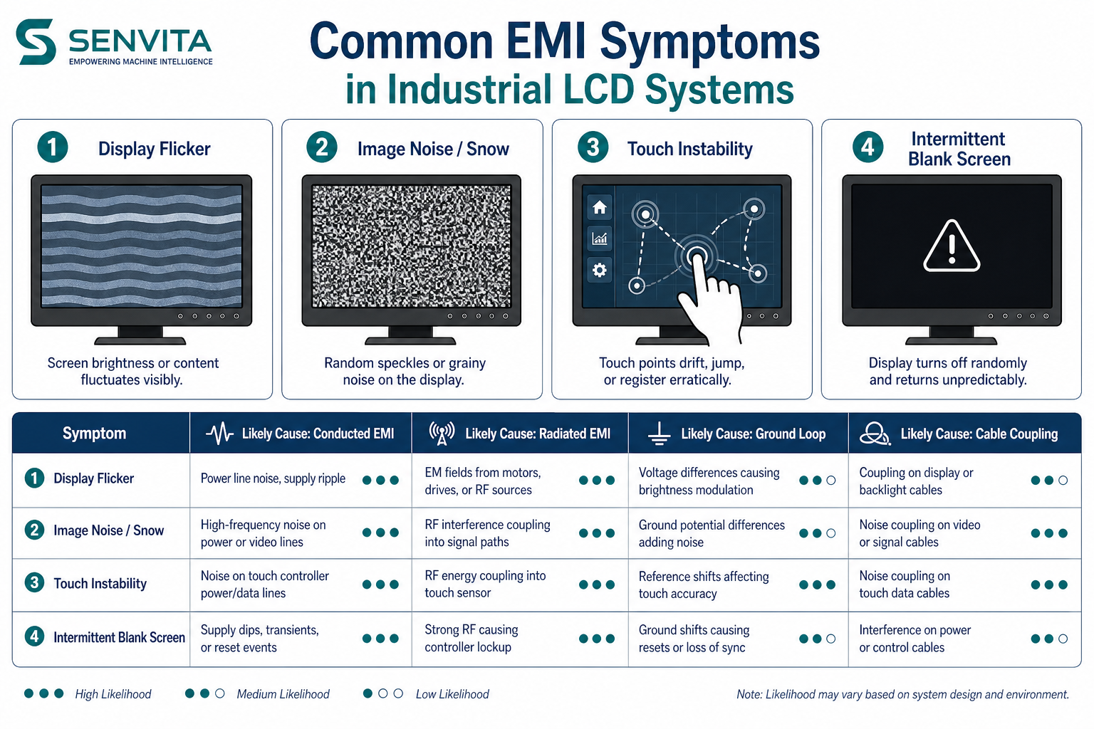
Random line artifacts on an HMI can look like short vertical bars, thin horizontal streaks, intermittent colored lines, or a burst of noise that appears only during boot or vibration. In many industrial systems these are not panel-glass defects; they are symptoms of marginal signal integrity, ground disturbance, or an unstable source timing relationship.
Definition
A random line artifact is an intermittent visible line that is not fixed in the same location like a dead column defect. It often moves, changes color, appears under stress, or disappears when the cable is reseated. That behavior strongly suggests an electrical or mechanical intermittency rather than a permanent panel failure.
- Common triggers: motor start, relay switching, nearby inverter noise, cable movement, and wake/sleep transitions.
- Likely layers: differential signal integrity, connector contact resistance, grounding, source timing, and panel initialization.
- Distinguish from: fixed dead pixels, permanent column defects, and backlight non-uniformity.
Problem: Lines appear when a motor or relay switches
Cause: Conducted and radiated EMI can couple into the display cable or reference ground, causing the receiver to sample corrupted data. Poor cable shielding or a shared noisy return path makes the problem worse.
Solution: Separate high-current loads from the display return, improve shield termination, shorten the cable where possible, and verify that the receiver timing margin is not already too tight. For the broader EMI path, see EMI Troubleshooting for Industrial Display and Flicker & EMI Troubleshooting Guide.
Problem: A single line appears only during boot or resume
Cause: The display may be sampling invalid data before the source has fully initialized, or the panel may need a different reset order. In interface-limited designs, a marginal clock or DE polarity can show up only during the first frames after wake-up.
Solution: Add deterministic boot delays, hold reset until all rails are stable, and confirm that the source timing matches the panel reference mode. If the HMI uses a different bridge or signaling family, compare the options in LVDS vs MIPI Industrial Display and Display Subsystem Architecture for HMI.
Problem: Moving the cable changes the line pattern
Cause: Intermittent connector contact, damaged shield termination, or impedance discontinuity can create a fault that is mechanical as well as electrical. A line that changes when the harness is bent usually points to the interconnect rather than the panel.
Solution: Inspect the connector retention, recheck the crimp or solder joints, perform a continuity test under flex, and compare with a known-good harness. If the system uses a high-density panel interface, review the selection logic in Choose TFT LCD for Industrial HMI.
Validation
Validation should reproduce the artifact under stress and then eliminate one variable at a time.
- Test with a known-good cable, then a known-good source, then a known-good panel.
- Observe the signal with an oscilloscope or eye diagram tool where available.
- Run vibration, EMI, and thermal soak tests to see whether the artifact is environment-dependent.
- Record whether the line appears on one color channel, one interface lane, or all modes.
For the common root-cause framework, consult Flicker & EMI Troubleshooting Guide.
Related reading: EMI Troubleshooting for Industrial Display, LVDS vs MIPI Industrial Display, Display Subsystem Architecture for HMI.